4.2 Widely Accepted Fault Models
Many fault models were proposed [1,2], but the ones widely accepted are as follows
• Stuck-at fault model: In this model, faults are fixed (0 or 1) value to a net which is an input or an output of a logic gate or a flip-flop in the circuit. If the net is stuck to 0, it is called stuck-at-0 (s-a-0) fault and if the net is stuck to 1, it is called stuck-at-1 (s-a-1) fault. If it is assumed that only one net of the circuit can have a fault at a time, it is called single stuck-at fault model. Without this assumption, it is called multiple stuck-at fault model. This has been observed though fabrication and testing history, that if a chip is verified to be free of single stuck-at faults, then it can be stated with more than 99.9% accuracy that there is no defect in the silicon or the chip is functionally (logical) normal. Further, single-stuck at fault is extremely simple to handle in terms of DFT required, test time etc.; this will be detailed in consequent lectures. So single stuck-at fault model is the most widely accepted model.
• Delay fault model: Faults under this model increase the input to output delay of one logic gate, at a time.
• Bridging Fault: A bridging fault represents a short between a group of nets. In the mot widely accepted bridging fault models, short is assumed between two nets in the circuit. The logic value of the shorted net may be modeled as 1-dominant (OR bridge), 0-dominant (AND) bridge. It has been observed that if a circuit is verified to be free of s-a faults, then with high probability it can be stated that there is no bridging fault also.
Next we elaborate more on the stuck-at fault model which is most widely accepted because of its simplicity and quality of test solution.
4.3 Single Stuck-at Fault Model
For single stuck-at fault model it is assumed that a circuit is an interconnection (called a netlist) of Boolean gates. A stuck-at fault is assumed to affect only the interconnecting nets between gates. Each net can have three states: normal, stuck-at-1 and stuck-at-0. When a net has stuck-at-1 (stuck-at-0) fault it will always have logic 1(0) irrespective of the correct logic output of the gate driving it. A circuit with n nets can have 2n possible stuck-at faults, as under single-at fault model it is assumed that only one location can have a stuck-at-0 or stuck-at-1 fault at a time. The locations of stuck-at faults in the AND gate G1 (in the circuit of Figure 2) are shown in Figure 6 with black circles. G1 is a 5 input AND gate thereby having 5 input nets and an output net. So, there are 12 stuck-at faults possible in the gate.
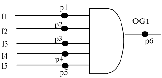
Figure 6: AND gate with stuck-at fault locations