2. Piston pumps
Piston pumps are meant for the high-pressure applications. These pumps have high-efficiency and simple design and needs lower maintenance. These pumps convert the rotary motion of the input shaft to the reciprocating motion of the piston. These pumps work similar to the four stroke engines. They work on the principle that a reciprocating piston draws fluid inside the cylinder when the piston retracts in a cylinder bore and discharge the fluid when it extends. Generally, these pumps have fixed inclined plate or variable degree of angle plate known as swash plate (shown in Figure 5.3.5 and Figure 5.3.6). When the piston barrel assembly rotates, the swash plate in contact with the piston slippers slides along its surface. The stroke length (axial displacement) depends on the inclination angle of the swash plate. When the swash plate is vertical, the reciprocating motion does not occur and hence pumping of the fluid does not take place. As the swash plate angle increases, the piston reciprocates inside the cylinder barrel. The stroke length increases with increase in the swash plate angle and therefore volume of pumping fluid increases. During one half of the rotation cycle, the pistons move out of the cylinder barrel and the volume of the barrel increases. During another half of the rotation, the pistons move into the cylinder barrel and the barrel volume decreases. This phenomenon is responsible for drawing the fluid in and pumping it out. These pumps are positive displacement pump and can be used for both liquids and gases. Piston pumps are basically of two types:
- Axial piston pumps
- Radial piston pumps
2.1 Axial Piston Pump
Axial piston pumps are positive displacement pumps which converts rotary motion of the input shaft into an axial reciprocating motion of the pistons. These pumps have a number of pistons (usually an odd number) in a circular array within a housing which is commonly referred to as a cylinder block, rotor or barrel. These pumps are used in jet aircraft. They are also used in small earthmoving plants such as skid loader machines. Another use is to drive the screws of torpedoes. In general, these systems have a maximum operating temperature of about 120°C. Therefore, the leakage between cylinder housing and body block is used for cooling and lubrication of the rotating parts. This cylinder block rotates by an integral shaft aligned with the pistons. These pumps have sub-types as:
- Bent axis piston pumps
- Swash plate axial piston pump
2.1.1 Bent-Axis Piston Pumps
Figure 5.3.5 shows the schematic of bent axis piston pump. In these pumps, the reciprocating action of the pistons is obtained by bending the axis of the cylinder block. The cylinder block rotates at an angle which is inclined to the drive shaft.The cylinder block is turned by the drive shaft through a universal link. The cylinder block is set at an offset angle with the drive shaft. The cylinder block contains a number of pistons along its periphery. These piston rods are connected with the drive shaft flange by ball-and-socket joints. These pistons are forced in and out of their bores as the distance between the drive shaft flange and the cylinder block changes. A universal link connects the block to the drive shaft, to provide alignment and a positive drive.
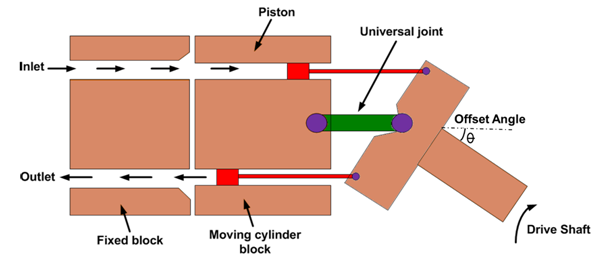
Figure 5.3.5 Bent axis piston pump
The volumetric displacement (discharge) of the pump is controlled by changing the offset angle. It makes the system simple and inexpensive. The discharge does not occur when the cylinder block is parallel to the drive shaft. The offset angle can vary from 0° to 40°. The fixed displacement units are usually provided with 23° or 30° offset angles while the variable displacement units are provided with a yoke and an external control mechanism to change the offset angle. Some designs have arrangement of moving the yoke over the center position to reverse the fluid flow direction. The flow rate of the pump varies with the offset angle θ. There is no flow when the cylinder block centerline is parallel to the drive shaft centerline (offset angle is 0°). The total fluid flow per stroke can be given as:
| (5.3.1) |
The flow rate of the pump can be given as:
| (5.3.2) |
here,  |
(5.3.3) |
where S is the piston stroke, D is piston diameter, n is the number of pistons, N is the speed of pump and A is the area of piston.