1.1 Unbalanced Vane pump
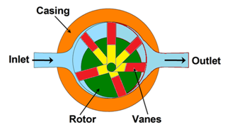
Figure 5.3.2 Unbalanced vane pump
In practice, the vane pumps have more than one vane as shown in figure 5.3.2. The rotor is offset within the housing, and the vanes are constrained by a cam ring as they cross inlet and outlet ports. Although the vane tips are held against the housing, still a small amount of leakage exists between rotor faces and body sides. Also, the vanes compensate to a large degree for wear at the vane tips or in the housing itself. The pressure difference between outlet and inlet ports creates a large amount of load on the vanes and a significant amount of side load on the rotor shaft which can lead to bearing failure. This type of pump is called as unbalanced vane pump.
1.2 Balanced vane pump
Figure 5.3.3 shows the schematic of a balanced vane pump. This pump has an elliptical cam ring with two inlet and two outlet ports. Pressure loading still occurs in the vanes but the two identical pump halves create equal but opposite forces on the rotor. It leads to the zero net force on the shaft and bearings. Thus, lives of pump and bearing increase significantly. Also the sounds and vibrations decrease in the running mode of the pump.

Figure 5.3.3 Balanced Vane Pump