Exercise 7.6 All the exercise problems provided for the TMM in previous chapter can be attempted with the FEM. Compare your results obtained by TMM and FEM and interpret physically observations made. Whether TMM under-estimate and FEM over-estimate natural frequencies?
Exercise 7.7 For a continuous shaft of 3 m length and 0.03 m diameter, obtain torsional natural frequencies up to fifth mode and plot corresponding mode shapes for the following boundary conditions (i) fixed-free and (ii) fixed-fixed. Use finite element method. Compare natural frequencies with closed form analytical solutions, and perform a converge study by increasing the number of elements (i.e., 5, 10, 50, and 100) and discuss the result. The following properties of the shaft should be taken: ρ = 7800 kg/m3 and G = 0.8 × 10¹¹ N/m2 .
Exercise 7.8 For a continuous shaft of 3 m length and 0.03 m diameter, obtain torsional natural frequencies up to fifth mode and plot corresponding mode shapes for the following boundary conditions (i) a cantilevered shaft with a disc at the free end (ii) a fixed-fixed shaft with a disc at the midspan,. The polar mass moment of inertia of the disc Ip = 0.02 kg-m2 . Use finite element method. Compare natural frequencies with closed form analytical solutions. The following properties of the shaft should be taken: ρ = 7800 kg/m3 and G = 0.8 × 10¹¹ N/m2 .
Exercise 7.9 Obtain torsional natural frequencies and mode shapes of an epi-cyclic gear train as shown in Figure E7.9. Find also the location of nodal point on the shaft. The gear mounted on shaft ‘B' is a planetary gear and the gear on shaft ‘A' is a sun gear. Consider the polar mass moment of inertia of the shaft, the arm, and gears as negligible. Shaft ‘A' has 5 cm of diameter and 0.75 m of length and shaft ‘B' has 4 cm of diameter and 1.0 m of length. Take the modulus of rigidity of the shaft G equals to 0.8 × 10¹¹ N/m2 , the polar mass moment of inertia of discs are IA = 24 Nm2 and IB = 10 Nm2 . Use FEM. [ Hint : Obtain the gear ratio n AB between shaft A and B using epi-cyclic gear train, now obtain the equivalent two mass rotor system for which closed form expressions of natural frequencies are available]
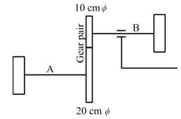
Figure E7.9 An epi-cyclic geared system
Exercise 7.10 A rod has two rigid discs at either ends and it is supported by two torsional springs of stiffness kt1 = kt2 = kt at each end of the rod. Use the following parameters: the mass polar moment of inertia of the disc Ip = 0.002 kg-m2 , torsional stiffness of the spring at free end kt = 2 × 10² Nm/rad, length of the rod l = 0.5 m, diameter of the rod d = 0.01 m, mass density of the rod material ρ = 7800 kg/m3 and modulus of rigidity of the rod material G = 0.8 × 10¹¹ N/m2 . Obtain natural frequencies of the system by considering rod as two elements only.
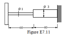
Exercise 7.11 Find torsional natural frequencies of a cantilever rotor system as shown in Figure E7.11. Consider the shaft as massless and is made of steel with the modulus of rigidity of 0.8(10)11 N/m2 and mass density of 7800 kg/m3 . A disc is mounted at the free end of the shaft with the polar mass moment of inertia 0.01 kg-m2 . In the diagram all dimensions are in cm. Use the FEM and compare results with the TMM.
Exercise 7.12 Find torsional natural frequencies and mode shapes of the rotor system shown in Figure E7.12. B1 and B2 are frictionless bearings, which provide free-free end condition; and D1 , D2 , D3 and D4 are rigid discs. The shaft is made of the steel with the modulus of rigidity G = 0.8(10)11 N/m2 and a uniform diameter d = 20 mm. Various shaft lengths are as follows: B1D1 = 150 mm, D1D2 = 50 mm, D2D3 = 50 mm, D3D4 = 50 mm and D4D2 = 150 mm. The mass of discs are: m 1 = 4 kg, m 2 = 5 kg, m 3 = 6 kg and m 4 = 7 kg. Consider the shaft as mass-less. Consider discs as thin and take diameter of discs as d1 = 8 cm, d2 = 10 cm, d3 = 12 cm, and d4 = 14cm.
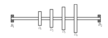
Figure E7.12 A multi-disc rotor system
Exercise 7.13 Multiple choice type questions, choose single answer
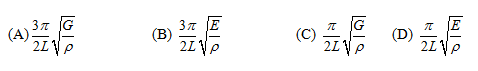
(i) For the torsional vibration of a uniform rod with distributed inertia and stiffness properties, the fundamental natural frequency expression is given as
(ii) A reciprocating engine has crank revolving mass 4 kg at a radius of 5 cm, the connecting rod with a mass of 6 kg and length of 30 cm with centre of gravity at 1/3 of its length from crack pin, and piston has a mass of 5 kg. What would be the total equivalent revolving mass of the reciprocating engine for the analysis of torsional vibration
![]()
Keys : (i) C (ii) C
References:
- Dixit, U.S., 2009, Finite Element Methods for Engineers , Cengage Learning, New Delhi.
- Reddy, J.N., 1993, An Introduction to the Finite Element Method , McGraw-Hill, New York.
- Huebner, K.H., Dewhirst, D.L., Smith, D.E., and Byrom, T.G., 2001, The Finite Element Method for Engineers , Fourth Edition, Wiley-Interscience Publication, John Wiley & Sons, Inc., New York.
- Cook, R.D., Malkus, D.S., Plesha, M.E., and Witt, R.J., 2002, Concepts and Applications of Finite Element Analysis , 4th edition, John Wiley & Sons, New York, 2002.
- Bathe, K.J., 1982, Finite Element Procedures in Engineering Analysis, Prentice-Hall, Englewood Cliffs, NJ.
- Kreyszig, E, 2006, Advanced Engineering Mathematics , John Wiley & Sons, Hoboken.
- Meirovitch, L., 1986, Elements of Vibration Analysis , McGraw Hill Book Co., NY.
- Rao, J.S., 1992, Advanced Theory of Vibration , Wiley Eastern Limited, New Delhi.
- Hughes, T.J.T., 1986, The Finite Element Method , Prentice-Hall, Englewood Cliffs, NJ.
- Thomson, W.T. and Dahleh, M.D., 1998, Theory of Vibration with Applications, Fifth Edition, Pearson Education Inc., New Delhi .
- Zienkiewicz, O.C., and Taylor, R.L., 1989, The Finite Element Method, 3rd ed. McGraw-Hill, New York.