Using equations (g) or (h), natural frequencies can be obtained as
In the former method, relative amplitudes of rotational displacements (i.e. mode shapes) are obtained by substituting these natural frequencies one at a time in equation (d). In latter method, mode shapes
(eigen vectors) are obtained by the eigen value analysis of the matrix [D] = [M]−1 [K]. The eigen value will give the square of natural frequencies and eigen vectors will give mode shapes as described above. Mode shapes are shown in Fig. 7.29 for first three modes only. It should be noted that relative rotational displacements obtained from equation (d) are actual displacements and no further scaling by the gear ratio is required as we did for the equivalent geared system. The rotational displacements of discs C and D are related (i.e., these are not independent) with the rotational displacement of disc B with respective gear ratio. These rotational displacements have been obtained with these relations only for the present case for completeness of mode shapes.
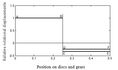
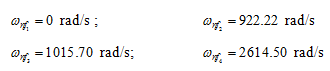
Figure 7.29(a) Mode shape of the geared system for ωnf1 = 0
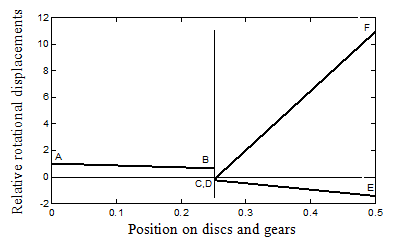
Figure 7.29(b) Mode shape of the geared system for ωnf2 = 922.22 rad/s
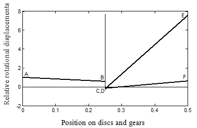
Figure 7.29(c) Mode shape of the geared system for ωnf3 = 1015.70 rad/s
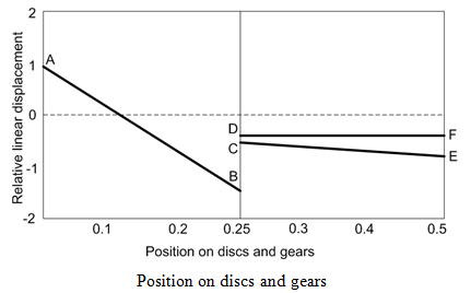
Figure 7.29(d) Mode shape of the geared system for ωnf4 = 2623.8 rad/s
Concluding Remarks :
To summarise, in the present chapter torsional vibrations of rods by the continuous system approach is initially presented. The Hamilton's principle is used to obtain the governing equations, and associated geometric (i.e., related to the rotational displacement) and natural boundary (i.e., related to the torque) conditions. The form of the governing equation is similar to the wave equation. The closed form solutions for simple boundary conditions are presented by method of separation of variables, and corresponding natural frequencies (eigen frequencies) and mode shapes (eigen functions) are tabulated and plotted, respectively. Since for more complex rotor-support systems obtaining the closed form solution is very difficult and some times it is impractical, hence a need of an approximate method (e.g., FEM) is felt. The finite element analysis for the torsional vibration is presented by the Galerkin and Raleigh-Ritz methods. The analysis presented for the torsional case is also of the similar form as that of axial vibrations of rods. In that case the axial displacement will replace the rotational displacement, and the axial force will replace the torque. The axial stiffness of the rod is given as ka = EA / l (where A is the cross sectional area of the rod), whereas the torsional stiffness is given as kt = GJ / l . With these analogies all the analysis of the torsional vibration can be used for axial vibrations also. The finite element analysis is extended to rotors with branched systems also by developing elemental equations for the gear-pair element. However, the flexibility of the gear teeth is not considered and they are assumed to be rigid. In some cases the coupling is present between the transverse and axial directions, when a rod has initial constant tension or compression. Due to initial constant tension, it is expected that the effective transverse stiffness increases and due to this the natural frequency also increases. However, for initial constant compression of the rod the transverse stiffness decreases and correspondingly the natural frequency also decreases. In the limit when this compressive load is equal to or greater than the buckling load the stiffness and so natural frequency of the system becomes zero. This case will be considered while discussing the transverse vibrations in subsequent chapters. Another issue we have not touched in the present chapter that is as how to tackle the increasing number of matrix size while using FEM. There are condensation schemes (or the reduction schemes ) that allow elimination of the unwanted DOFs to be eliminated from the assembled system matrices and it will be discussed during the application of the FEM in transverse vibrations.