Now equation (a) and (c) can be assembled to get the global governing equation
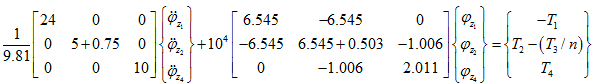 |
(d) |
At junction, we have T2 – (T3 / n ) = 0; and discs at ends are free, hence, T1 = T4 = 0. Thus, on application of boundary conditions equation (d) takes the following form for free vibrations
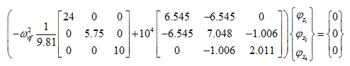 |
(e) |
From which we can write
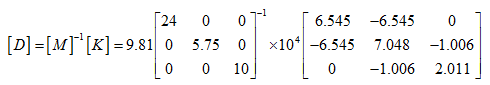 |
(f) |
From the eigen value analysis, natural frequencies and mode shapes can be obtained from the matrix [ D ] and are given as
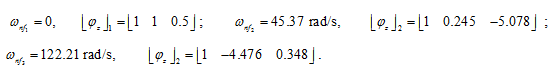
The eigen vector gives relative rotational displacement at various node locations. For rigid boy mode, it could be seen that the nodes 1 and 2 have rotational displacement of 1 unit each, whereas node 4 has rotational displacement of 0.5 unit because of gear ratio effect. For obtaining rotational displacement at node 3, we need to use the gear ratio which gives rotational displacement at node 3 as 0.5 unit. The same has to be followed for other modes. Results could be compared with Example 6.12 by TMM and it is quite close to that.
Example 7.9 Obtain torsional natural frequencies of a branched rotor system as shown in Figure 7.25. Take the polar mass moment of inertia of rotors and gears as: IpA = 0.01 kg-m2 , IpE = IpB = 0.005 kg-m2 and IpF = IpC = IpD = 0.006 kg-m2 . Take gear ratio between various gear pairs as: nBC = 3 and nBD = 4 . Shaft lengths are: lAB = lCE = lDF = 0.25 m and its diameters are dAB = 0.03 m, dCE = 0.02 m, and dDF = 0.02 m. Take the shaft modulus of rigidity G = 0.8 × 10¹¹ N/m2 .
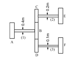
Figure 7.25 A branched system with gears
Solution : The branched system is divided into three elements. Figure 7.25 shows various element numbers of the branched rotor system. Now various element equations can be written as follows:
Element (1): Figure 7.26 shows element (1) with nodal variables. Since this shaft element is the input shaft, hence, there is no change in the inertia terms as well as in the stiffness terms.
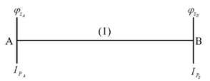
Figure 7.26 Element (1)
Equations of motion for element (1) can be written as (on neglecting the inertia of the shaft)
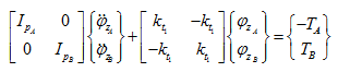 |
(a) |
Element (2): Figure 7.27 shows element (2) with nodal variables. The actual nodal variable at gear C is related with the nodal variable of gear B, hence nodal variable of gear B is used. This affects both the mass and stiffness matrices as well as the internal torque vector.
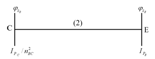
Figure 7.27 Element (2)