7.3 Development of the Finite Element for a Simple Gear-pair
Figure 7.21 shows a gear-pair element. The counter clockwise direction is taken as the positive direction for all rotational displacements. It is the practice and convenient in finite element formulations. The gear ratio, n , (which is an inverse of the speed ratio) is defined as
 |
(7.104) |
where ω1 and ω2 are the rotational speed of the driver (pinion or gear 1) and driven (gear 2) shafts.
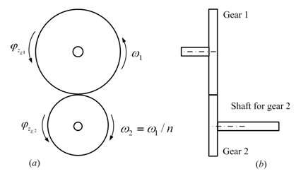
Figure 7.21 A simple gear-pair element
For no slip and no backlash conditions, and for perfectly rigid gear teeth (it is assumed that gear tooth are not providing any torsional flexibility; however, in the real case bending of the tooth and the deformation at the contact zone due to the Hertzian contact stress might give rise to appreciable amount of torsional flexibility, especially for the case when the power-transmission is very high) from Figure 7.21, we have
(7.105) |
where φzg1 and φzg2 are rotational displacements of gears 1 and 2, respectively. Since φzg2 is defined in terms of φzg1, we can eliminate φzg2 from the state vector of the system. It should be noted we are not obtaining an equivalent gear system as such as obtained earlier.
The Mass Matrix : The equivalent inertia force of the gear-pair with respect to the reference shaft 1 is given as (refer chapter 6 for more details regarding equivalent polar mass moment of inertia force of discs in two shaft systems with different speeds)
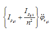
where Ipg1 and Ipg2 are polar mass moment of inertia of actual gears 1 and 2, respectively. Above expression could be written in the mass matrix form as
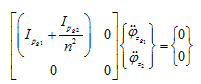 |
(7.106) |
The Stiffness Matrix : The stiffness matrix of the shaft element connected to gear 2 will have to be modified, since the rotational deflection of the left hand side of that shaft element is now equal to (φz1 = −φzg1 / n ) instead of φzg2 (see Figure 7.22). Let us assume that the right hand side end of the shaft has rotational displacement φz2 .
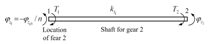
Figure 7.22 An equivalent shaft element connected to gear 2
The potential energy of the shaft element in Figure 7.22 is
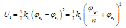 |
(7.107) |
The work done is give as
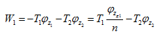 |
(7.108) |
On applying the Raleigh-Ritz method, we get
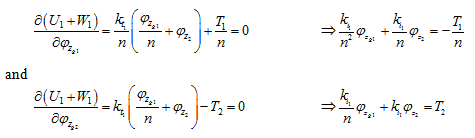 |
(7.109)
(7.110) |