Case 2: A disc having infinite size
For μ → ∞ (i.e., a disc for which all the mass is concentrated at a relatively large radius so that, Id → ∞.) no finite angular displacement φx is possible, since it would require an infinite torque, which the shaft cannot furnish. The disc remains parallel to itself and the shaft is much stiffer than without the disc effect (i.e., μ = 0). From equation (5.37) for μ → ∞, we get
| (5.41) |
The critical speed for the present case is two times more as compared to Case I. It should be noted that for the present case one of the solution ![]() is considered as not feasible. However, when μ → - ∞ it is a feasible solution and the natural frequency of the system would be zero. This particular issue will be considered in the next section by replacing the thin disc with a long stick, which requires a separate analytical treatment; and it has been treated only for the pure rotational motion.
is considered as not feasible. However, when μ → - ∞ it is a feasible solution and the natural frequency of the system would be zero. This particular issue will be considered in the next section by replacing the thin disc with a long stick, which requires a separate analytical treatment; and it has been treated only for the pure rotational motion.
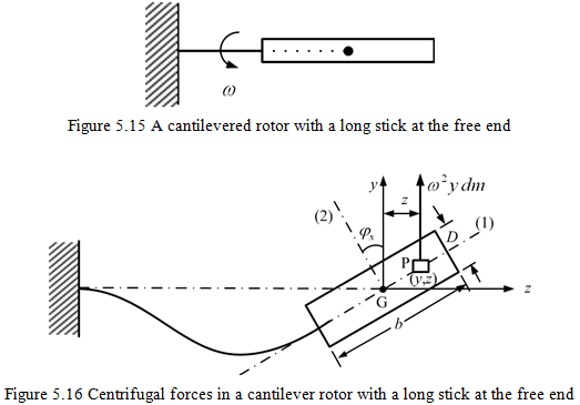
5.3.2 A cantilever rotor with a long stick
For the present case, the disc at free end of a cantilever rotor has considerable amount of length as shown in Figure 5.15. The couple of centrifugal forces for this case are such; it tries to push away the rotor from the static equilibrium position angularly as shown in Figure 5.16. For the present case also the (forward) synchronous whirl condition is assumed. For the thin disc case, the couple of centrifugal forces try it to bring back to the static equilibrium position angularly. In Figure 5.16 principal axes directions are (1) and (2). The coordinate of a point mass dm is (y, z).
For the present case, it is assumed that no unbalance is present in the rotor (i.e., the rotor geometrical centre C and the centre of gravity G are coincident) and the centre of gravity G of the body is positioned in the axis of rotation x (i.e., no linear displacement, δ = 0). Hence, there is no net centrifugal force, mω2δ (where m is the mass of the long stick), and only a moment is present. The force on a particle is ω2y dm and its moment arm about x-axis is z (Fig. 5.16), so that the moment is
| (5.42) |
For the thin disc we have z = yφx (Fig. 5.12c) ), so above equation for that case (thin disc case) reduces to dMyz = ω2y2φxdm (see equation . Now for present case (long long stick case) the whole body, we have
| (5.43) |
Let 1 and 2 be the principal axes along the longitudinal and transverse directions of the long stick (Fig. 5.16), respectively. Let the mass moment of inertia about these principal axes be I1 and I2, which are the polar and diametral mass moments of inertia, respectively. This set of axes is at an angle φx of with respect to the y-z axes as shown in Figure 5.16. The product of inertia (it is analogous to the shear stress in the subject of the strength of materials) about y-z axes is defined as
| (5.44) |
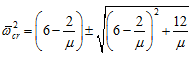
Here the angular deformation, φx, is assumed to be small. For the thin disc I1 = Ip = 2Id and I2 = Id so that equations (5.44) and (5.43) gives Myz = ω2Id,φx which is same as equation . However, for a disc of the diameter D and the thickness b (Fig. 5.16), we have for the present case
| (5.45) |
On substituting equations (5.44) and (5.45) into equation (5.43), we get
| (5.46) |
For the moment of centrifugal forces is to be zero, from above equation, we have
![]()
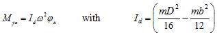
and it becomes negative for b > 0.866D (i.e., for the long stick) and it is positive for b < 0.866D ( i.e., for the thin disc).
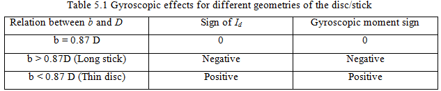
Table 5.1 gives the summary of gyroscopic moment with its sign for different ratio of b and D. Equation (5.46) can be written as
 |
(5.47) |
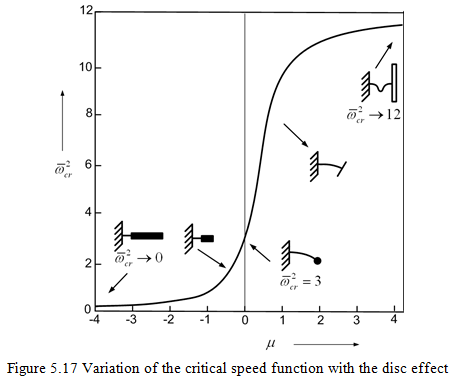
It can be found that the net resultant force will also be same for the long stick and the thin disc, when we consider both the linear and angular motions simultaneously. Thus, the critical speed analysis of the previous section will be valid for the present case also, when we consider both the linear and angular motions simultaneously. Hence, Figure 5.14 of the previous case will still be applicable for a range of thin discs. However, the plot from the above equation will represent both the long stick and thin disc cases as shown in Fig. 5.17, since the form of net moment equations (5.29) and (5.47) are identical. Hence, from equation (5.38), we have
 |
(5.48) |
with
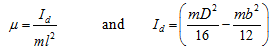 |
(5.49) |
The condition for which the square root term in equation (5.48) remain always positive is
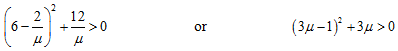 |
(5.50) |