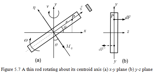
5.2.3 Gyroscopic moments in a rotating thin blade
In Figure 5.7, we have z-axis as the axis of spin and y-axis as the axis of precession. Let ξ and η are the two orthogonal principal axes of the thin rod, with ξ making an angle of θ with the x-axis. Due to the Coriolis component of acceleration the force at a point P, of the mass dm is given as
| (5.12) |
which acts along the spin axis (positive z-axis direction in Figure 5.7b). The moment due this force about η-axis is given as (with the moment arm of r)
| (5.13) |
The total moment of all particles above and below the η-axis is given as
| (5.14) |
with
| (5.15) |
From the parallel axis theorem, we have
| (5.16) |
where Ip = Izz is the polar moment of inertia. Since the rod is thin, hence we have Iξ ≈ 0. In view of equation (5.16), equation (5.14) reduces to
| (5.17) |
which is along the negative η-axis direction as shown in Figure 5.7. Taking component of moment Mη along the x-and y- axes, as
| (5.18) |
and
| (5.19) |
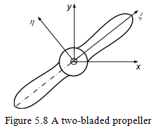
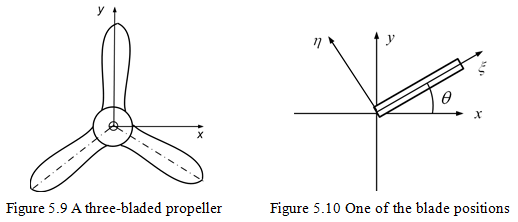
There are two gyroscopic moments, respectively, about the x- and y-axes. This comes because of the asymmetric body of revolution, i.e. Iη ≠ Iξ. From equations (5.18) and (5.19) it can be seen that Mxx and Myy are varying with θ, i.e. Mxx varies from 0 to 2Ipωv; and Myy varies from -Ipωv to Ipωv. The above analysis is applicable to the two-bladed propeller or the airscrew (Figure 5.8). The above analysis can be extended to a multi-bladed propeller (e.g., Fig. 5.9).
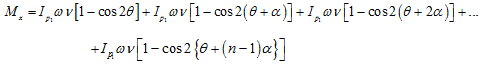
5.2.4 Gyroscopic moments in a multi-bladed propeller: Let n be the number of blades (n ≥ 3) and ![]() is equally spaced angle between two blades. Let us consider one of the blades (designate as 1), which is inclined to an angle θ with x-axis as shown in Figure 5.10. Let the moment of inertia of each blade about η-axis (i.e. perpendicular to the blade) be equal to Iη which in turn is equal to the polar mass moment of inertia of blade 1 alone, i.e.,
is equally spaced angle between two blades. Let us consider one of the blades (designate as 1), which is inclined to an angle θ with x-axis as shown in Figure 5.10. Let the moment of inertia of each blade about η-axis (i.e. perpendicular to the blade) be equal to Iη which in turn is equal to the polar mass moment of inertia of blade 1 alone, i.e., ![]() . Total polar moment of inertia of the airscrew about the axis of rotation (z-axis) is:
. Total polar moment of inertia of the airscrew about the axis of rotation (z-axis) is: ![]() .
.
Total moment about x-axis of blade 1 is given as
| (5.20) |
The location of other blades is given by the phase angle ![]() (the phase angle of various blades with respect to one of the reference blade would be
(the phase angle of various blades with respect to one of the reference blade would be ![]() , where a is the phase difference between two blades). Noting equation (5.20), on summing up the moments due to all n blades, we have
, where a is the phase difference between two blades). Noting equation (5.20), on summing up the moments due to all n blades, we have
 |
(5.21) |
or
| (5.22) |
which can be simplified as
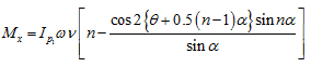 |
(5.23) |
Since ![]() for n > 2, we have
for n > 2, we have ![]() for all these values. Moreover, since
for all these values. Moreover, since ![]() for all value of n, we have
for all value of n, we have ![]() . Hence for all values of n > 2, from equation (5.23) we can write
. Hence for all values of n > 2, from equation (5.23) we can write
| (5.24) |
For n = 2, we have ![]() and
and ![]() , hence from equation (5.23), we get
, hence from equation (5.23), we get
| (5.25) |
The gyroscopic moment about y-axis for a blade as shown in Figure 5.10, which makes angle θ with x-axis, is
| (5.26) |
The total moment about y-axis for n blades with phase angles of ![]() is
is
| (5.27) |
The sine series in equation (5.27) will be zero for all values n > 2, hence
| (5.28) |
From equations (5.24) and (5.28), we can conclude that for the multi-bladed propeller with the number of blades equal to three or more is equivalent to a plane disc with the polar mass moment of inertia ![]() about the axis of rotation.
about the axis of rotation.
The objective of the present section was to have understanding of the gyroscopic moment in rotating components especially its direction of application. Now we shall deal with effects of gyroscopic moment, and the procedure of obtaining natural frequencies and critical speeds in simple single-mass rotor systems with the synchronous and asynchronous whirls (Den Hartog, 1984).