In previous chapter, we considered rotor-bearing systems for a single-mass rotor with different level of complexity at supports. We analysed the rotor system for the transverse (bending) translatory and rotary motions by considering the respective inertias. However, we neglected an important dynamic behaviour of the rotor system so called the gyroscopic effect, which predominates especially for high-speed rotors. In the present chapter also we shall still be dealing with a single-mass rotor system; and comeback to the assumption of rigid bearings in transverse directions. However, now we shall include the effect of gyroscopic effects and will explore the motion of the rotor for the synchronous as well as the asynchronous whirl. For the present case, we shall analyse the rotor system by two different approaches, firstly by the quasi-static analysis (which gives a better physical insight into the effect of gyroscopic effects, however, can be applied ideally to simple systems only), and secondly by the dynamic analysis (which can be easily extended to multi-DOF systems). An important aspect, which we will observe from the present chapter, is that because of the gyroscopic effect the whirl natural frequency becomes dependent on the rotor spin speed. Another interesting phenomenon that can be observed is that the rotor can have the forward and backward whirling motions. Moreover, for the present case the distinction among the rotor spin speed, the whirl natural frequency, and the critical speed will be made clearer.
When a relatively large disc (or a rotor with a large polar mass moment of inertia) spins at a very high speed about its longitudinal (polar) axis, then it has a large angular momentum and it is the main characteristics of rotors to carry a tremendous amount of the rotary power. However, if it has precession (slow or fast) about its transverse (diametral) axes, which comes due to flexibility of the shaft and/or bearings, then it develops change in the angular momentum due to change in its direction. This leads to an inertia moment called the gyroscopic moment. Basically the gyroscopic moment develops due to the Coriolis acceleration component and it will be shown subsequently.
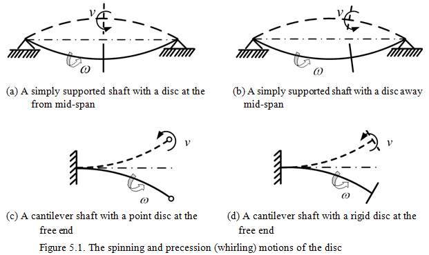
Figures 5.1(a) and (b) show the motion of a disc in a simply supported shaft (i.e., a Jeffcott rotor), when the disc is at the mid-span and at an offset positions, respectively. For the former case no gyroscopic effect would be present, since during whirling of the disc no precession motion takes place about its diameter. For the latter case, the precession of the disc, v, about its diametral axes takes place along with the spinning, ω, about the polar axis. This leads to the gyroscopic moment on the disc and it depends upon the spin speed, the precession velocity and polar mass moment of inertia of the rotor. Rotor systems with a point mass (with a negligible polar mass moment of inertia) and a thin disc (with an appreciable polar mass moment of inertia) are shown in Figures 5.1(c) and (d), respectively. The critical speeds of these rotor systems will not the same. This is due to the fact that centrifugal forces of particles of the disc do not lie in one plane during motion and thus form a moment tending to straighten the shaft and it will be discussed subsequently in more detail. Whereas in the case of point mass no such moment would be produced by centrifugal forces.
5.1 Angular Momentum
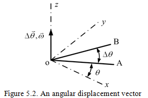
Let in Fig. 5.2, OA rotates about the z-axis in the x-y plane and OB is the position it takes after an infinitesimal time interval. Let Δθ be the infinitesimal angular displacement of OA, it is the angular displacement vector along z-axis. Similarly, the angular velocity, angular acceleration and angular momentum are also vector quantity. A change in the magnitude and direction of angular velocity results in the angular acceleration.The gyroscopic moment can be understood using the principle of angular momentum.
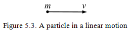
Let a particle of mass, m, is moving with a velocity, v. From Figure 5.3, the linear momentum, L, is defined as
| (5.1) |
The direction and sense of the linear momentum are same as the linear velocity.
Now, referring to Figure 5.4(a) in which a point mass m is revolving in a circle with a radius r in a plane, the angular momentum is defined as the moment of linear momentum
| (5.2) |
where Ip is the polar mass of inertia of particle of mass, m, about it’s axis of rotation o; and ω is the angular velocity of link OA. The direction of the angular momentum will be same as the angular velocity.
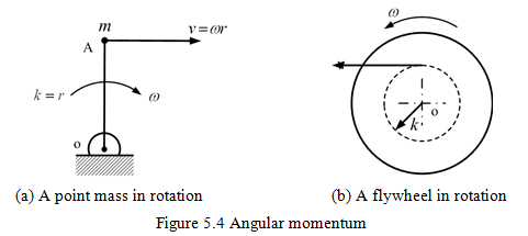
Referring to Figure 5.4(b) in which a flywheel of the mass m and of the radius of gyration k is rotating with an angular speed of, ω, the angular momentum of the flywheel is given as
| (5.3) |
The radius of gyration is an imaginary radius at which all the mass of the flywheel is assumed to be concentrated so as to have the same angular momentum as that of the actual flywheel.
5.2 Gyroscopic Moments in Rotating Systems
In the present section, the concept of the gyroscopic moment will be introduced with the help of simple rotating systems, e.g., discs and propeller blades. These basic concepts you might have studied to some extent in the subject of dynamics of machinery (Wrigley, et al., 1969; Bevan, 1984; Mabie and Reinholts, 1987; Rao and Dukkipati, 1995).
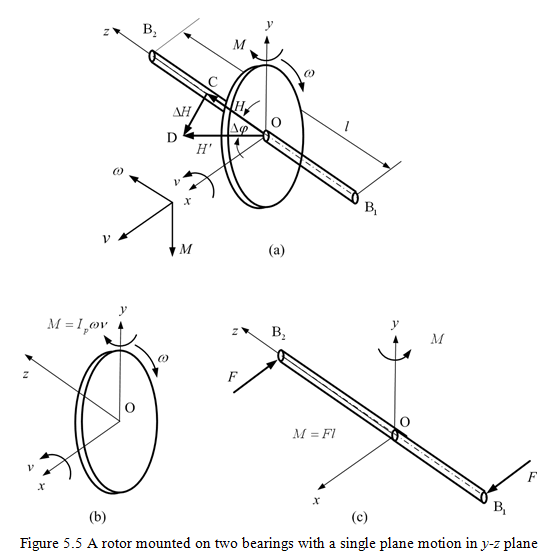
5.2.1 Motion of a rotor mounted on two bearings
Let us assume that a rotor with a flexible massless shaft carrying a disc is constraint to move in a vertical (single) plane. It is assumed that the constraint is not providing any friction forces during the motion of the shaft in that plane. A rotor is spinning with a constant angular velocity, ω; the angular momentum, H, will be given by Ipω. Let x-y-z be the rectangular coordinate system (see Figure 5.5a), where oz is the spin axis, ox is the precession axis, and oy is the gyroscopic moment axis.