5.3 Synchronous Motion
We are considering the case of a perfectly balanced rotor, however, it is assumed to be whirling at its critical speed in slightly deflected position. In the presence of gyroscopic couple we expect the whirl frequency, v, would be different.However, in the present analysis the whirl frequency, v, of the shaft is assumed to be same as the spin speed of shaft, ω . Hence, the aim of the present section would be to obtain the synchronous critical speed (since v = ω is assumed). In other words the aim would be to obtain ω for which its value is equal to n or at what speed (or condition) the synchronous whirl would take place. This implies that a particular point of the disc, which is outside during whirling, it will always be outside; and the inside point will always remains inside; this motion is called the synchronous motion. The shaft fibres in tension always remain in tension while whirling, and similarly the compression fibres always remain in compression. Thus any individual point of the disc moves in a circle in a plane perpendicular to the undistorted centre line of the shaft. We will consider two representative cases of cantilever (overhung) rotors, firstly a thin disc at the free end and secondly a long stick at the free end.
5.3.1 A cantilever rotor with a thin disc
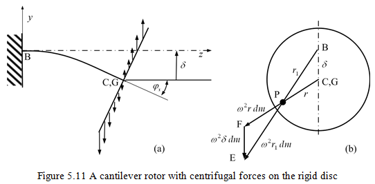
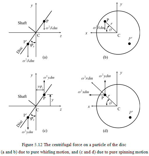
In the present section, a thin disc attached to a flexible massless shaft at its free end is considered (Fig. 5.11). In Fig. 5.11b, let points C and G are the disc geometrical centre and the disc centre of gravity, respectively. Since there is no unbalance in the rotor, hence points C and G are coincident. Let δ and φx are the linear and angular displacements of the disc at its geometrical centre, C. In fact the rotor is analysed for one plane motion (in y-z plane) with the linear and angular displacements in y-axis and x-axis directions, respectively, are considered similar to the case of previous section. The centrifugal force of a mass element dm at point P with coordinate (r, θ) is ω2r1 dm and is directed away from point B (a point on the bearing axis as shown in Figure 5.11b) with BP = r1. It can be considered as two force vectors, the one when dm is assumed to be rotated about the disc centre C (along CP) and the second force when C itself is rotating about B (along BC) with PC = r and BC = δ. The motion of the disc is considered in two parts, firstly the pure whirling and secondly the pure spinning. Two similar triangles BCP and EFP can be constructed to represent these three forces (Fig. 5.11b). The component in the vertical direction is ω2δ dm and is directed vertical down (this is due to the pure whirling). When these component forces are added together will give a force and no moment (Fig. 5.12 (a and b)). Whereas, the component in the radial direction is ω2r dm and is directed away from the disc centre C. When these component forces are added together will give zero force and the moment will be non-zero (Fig. 5.12 (c and d)). These will be illustrated now. The force ω2δ dm for various masses add together will give (Fig. 5.12 (a and b))
![]()
where m is the total mass of the disc. This force acts downward at C on the shaft. The aim is to obtain critical speed of the system (ωcr = ω = v).