Force components ω2r dm, all radiate from the centre of the disc C and in the plane of the disc. Hence, as such the forces will balance each other because of the symmetry, however, these will provide a net moment and it will be clear when we take its components in x and y directions. From Figure 5.12 (c and d), the y-component of the force, ω2r dm, is ω2rsinθ dm =ω2y dm (since y = rsinθ) and the moment arm of this elemental force is yφx. Thus the moment of the centrifugal force of a small particle dm is
![]()
and it will act on the shaft in the negative x-axis direction (ccw direction in Fig. 5.12c). The total moment Myz of centrifugal forces is
| (5.29) |
where Id is the diametral mass moment of inertia of the disc. Hence, the y-direction component forces balance themselves and these produce only the moment, Myz. Note that same could be obtained by the concept of change in the angular momentum. The x-component forces ω2rcosθdm =ω2x dm (since x = rcosθ) will balance themselves and produce no moment, since these forces are on the plane of the disc (Fig. 5.12(c and d)).
Thus in totality the end of the shaft is subjected to a force, mω2δ, and to a moment, Idω2φx, under the influence of this it assumes a linear deflection δ and an angular deflection φx. This can happen only at a certain speed ω, i.e. at the critical speed. Thus the calculation of critical speed is reduced to a quasi-static problem (in which the dynamic forces are considered as time-independent), Now the objective is to find at which value of ω the shaft will deflect δ and φx under the influence of Fy = mω2δand Myz= ω2Idφx. The direction of the force, Fy, and the moment, Myz, on the shaft is same as obtained in equations (5.7) and (5.29), respectively, since these have been obtained from the centrifugal force rather than the concept of the change in angular momentum.
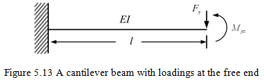
The linear angular displacement of the free end of the cantilever (fixed-free end conditions) beam as shown in Figure 5.13 will be (Timoshenko and Young, 1968)
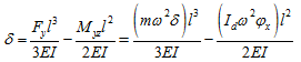 |
(5.30) |
and
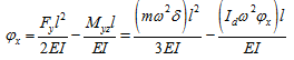 |
(5.31) |
It should be noted here that the above relations can also be developed for other boundary conditions such as simply supports, fixed-fixed, fixed-hinged etc. It requires calculation of influence coefficients by using the deflection theory of strength of materials. Now the above relations can be used to find critical speeds for the fixed-free boundary condition. Equations (5.30) and (5.31) can be rearranged as
| (5.32) |
and
| (5.33) |
This homogeneous set of equations can have a non-trivial solution for δ and φx only when the determinant vanishes
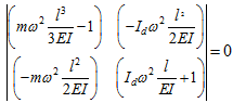 |
(5.34) |
which gives the frequency equation as
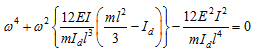 |
(5.35) |
This is the condition at which the rotor would have synchronous forward whirling and it will take place at critical speeds obtained from the above condition. To reduce the number of parameters involved in the above equation, defining the non-dimensional critical speed function, ![]() and the disc mass effect, μ, as
and the disc mass effect, μ, as
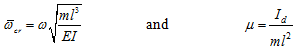 |
(5.36) |
Equation (5.35) can be written as
| (5.36) |
With the solution
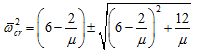 |
(5.37) |
The positive sign will give a positive value for ![]() or a real value for
or a real value for ![]() and the negative sign will give a complex value of the critical speed, which has no physical significance. Hence, we will have only single critical speed for a particular value of μ, so the negative sign may be ignored Plot of
and the negative sign will give a complex value of the critical speed, which has no physical significance. Hence, we will have only single critical speed for a particular value of μ, so the negative sign may be ignored Plot of ![]() versus μ is given in Figure 5.14.
versus μ is given in Figure 5.14.
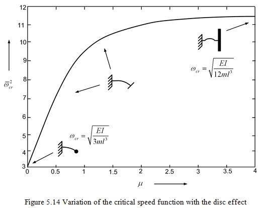
It should be noted that the critical speed of the rotor increases with the disc mass effect, μ. That means the effective stiffness of the rotor system increases due to the thin disc rather than a point-mass disc. This can be seen from Fig. 5.11(a) that the effect of centrifugal forces is to resist the tilting of the disc thereby increasing the effective stiffness of the rotor system. Overall for the synchronous whirl condition due to the gyroscopic effect the (forward) critical speed of the system increases. It will be shown that for anti-synchronous whirl condition due to gyroscopic effect the (backward) critical speed of the system decreases. Two limiting cases of Fig. 5.14 are discussed as follows:
Case 1: A disc having point-mass
For the disc effect μ = 0 (i.e., the concentrated mass of the disc) from equation (5.37), we have
| (5.38) |
Noting equation (5.36), above equation gives
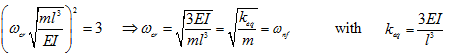 |
(5.39) |
where ωnf is the transverse natural frequency of the rotor system in the non-rotating condition. It gives the synchronous critical speed of disc having point-mass for the cantilever beam case. For this case in fact the gyroscopic effect is not present and critical speed is same as the transverse natural frequency of cantilever beam with a point mass at free end.