Equations of motion (4.63) and (4.64) of the disc can be written in matrix form as
(4.65) |
with
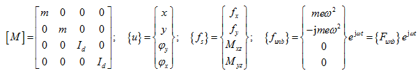
Noting ![]() , equations of motion take the following form
, equations of motion take the following form
(4.66) |
Noting equation (4.62), equation (4.66) becomes
(4.67) |
which gives
(4.68) |
with
![]()
where [H]-1 is the equivalent dynamic stiffness matrix, as experienced by the disc, of the shaft and the bearing system. Once the response of the disc has been obtained, from above equation for given unbalance force, the loading applied to the shaft by the disc can be obtained by equation (4.62). Then from equation (4.49) we can get shaft ends deflections {Xb} at each bearings, which is substituted in equation (4.41) to get bearing forces {Fb}. Alternately, bearing forces can be used directly from equation (4.48). Displacements and forces have the complex form; the amplitude and the phase information can be extracted from the real and imaginary parts. Amplitudes will be the modulus of complex numbers, and phase angles of all these displacements can be evaluated by calculating arctangent of the ratio of the imaginary to real components as given by equations (4.33) and (4.34).
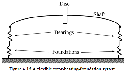
4.4 A Rotor on Flexible Bearings and Foundations
In some rotating machines, e.g. turbines, bearings themselves may be mounted on flexible foundations (Figure 4.16), which may in turn influence the motion of disc masses. In the present section, a very simple model of the foundation is considered by ignoring cross-coupled terms of the stiffness and the damping. For more detailed treatment on foundation effects, readers can refer to book by Krämer (1993).
The net displacement of the disc is given by the vector sum of (i) the disc displacement relative to shaft ends, plus (ii) that of shaft ends relative to the bearing, plus (iii) that of the bearing relative to the space. The theoretical analysis of the disc, the shaft and the bearing responses, and that of the force transmissibility of such a system, can be carried out in a similar manner to that described in the previous section. Additional governing equations related to the foundation are derived, and how to relate them with governing equations of the disc and bearings are detailed here.
The relationship between forces transmitted through bearings and displacements of shaft ends is governed by the bearing stiffness and damping coefficients. The form of governing equation is given by equation (4.41), which is
(4.69) |
In frequency domain takes the form, as
(4.70) |
where {xb} is the shaft end displacement relative to the bearing. Displacements of bearings with respect to foundations and forces transmitted through bearings are shown in Figure 4.17.
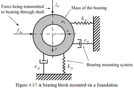
The bearing will respond in the horizontal direction for an external force fbx, which is governed by the following equation
(4.71) |
where xf is the horizontal displacement of the bearing, mb is the bearing mass of one bearing and kfx, cfx, kfy, cfy are the foundation stiffness and damping coefficients. Similarly, the response of the bearing in the vertical direction to a force fby is given as
(4.72) |
where yf is the vertical displacement of bearing. The displacement of the bearing will take the form
(4.73) |
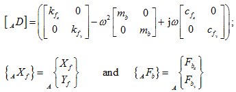
where Xf and Yf are complex displacements in the x and y directions, respectively. On substituting equation (4.73) in equations of motion (4.71) and (4.72), and on combining in the matrix form (for bearing A), it gives.
(4.74) |
with
For both bearings A and B, equations of form (4.74) can be combined as
(4.75) |
with
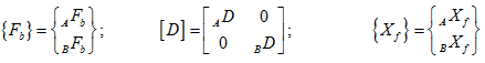
which gives relative displacements between bearings and the foundation, as
(4.76) |