where subscript b refers to the bearing and s refers to the shaft. On substituting equation (4.47) into equation (4.46), we get
(4.48) |
In equation (4.48), bearing forces are related to the reaction forces and moments at the shaft by the disc. On equating equation (4.41) and (4.48), we get
(4.49) |
Equation (4.49) relates the shaft end deflections to the reaction forces and moments on the shaft by the disc. The deflection at the location of the disc due to movement of shaft ends can be obtained as follows. Consider the shaft to be rigid for some instant and let us denote shaft end deflections in the horizontal direction to be Axb and Byb at ends A and B, respectively, as shown in Figure 4.14. These displacements are assumed to be small.
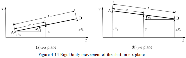
The linear displacement in the x-direction can be written as
(4.50) |
The angular displacement of the shaft in x-z plane will be
(4.51) |
Similarly, for the linear and angular displacements in the y- direction and in the y-z plane, respectively; we have
(4.52) |
and
(4.53) |
Equations (4.50)-(4.53) can be combined in a matrix form as
(4.54) |
with
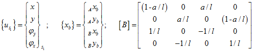
where subscript s1 represents that these displacements are due to rigid body motion of the shaft. For the unbalance excitation (or for the free vibration analysis), shaft displacements at bearing locations and at the disc centre vary sinusoidally such that
(4.55) |
where ω is the spin speed (or natural frequency in case of free vibrations). On substituting equation (4.55) into equation (4.54), we have
(4.56) |
On substituting equation (4.49) into equation (4.56), we get
(4.57) |
which gives the deflection of the disc due to the unbalance, when the shaft is rigid. Equation (4.57) will give deflection of the disc (at geometrical centre) that is caused by only the movement of shaft ends (rigid body movement) in flexible bearings. In order to obtain the net rotor deflection under a given load, we have to add the deflection due to the deformation of the shaft with respect to bearing locations also in equation (4.57). The deflection associated with flexure of the shaft alone has already been calculated in Chapter 2, which can be combined in a matrix form as
(4.58) |
with
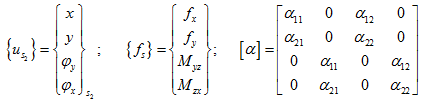
where subscript s2 represents that these displacements are due to the pure deformation of the shaft without any rigid body motion. For the unbalance excitation (or for the free vibration analysis), shaft reaction forces at the disc location and disc displacements vary sinusoidally, and can be expressed as
(4.59) |
On substituting equation (4.59) into equation (4.58), we get
(4.60) |
which is the deflection of disc due to the flexure of the shaft alone, without considering the bearing flexibility. The net deflection of the rotor that caused by the deflection of bearings plus that due to the flexure of the shaft, is then given by
(4.61) |
where {Us} contains absolute displacements of the shaft at the location of the disc. Equation describes the displacement of the shaft at the disc under the action of sinusoidal forces and moments applied at the disc (hence the matrix [D] is similar to the influence coefficient matrix). Equation can be written as
(4.62) |
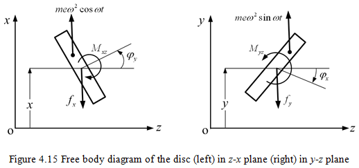
where the matrix [E] is similar to the stiffness matrix (it is equivalent stiffness of the shaft and bearings experienced at disc location). Equations of motion of the disc can be written in the x-direction and on the z-x plane (see Figure 4.15a), as
![]()
and
(4.63) |
Similarly, equations of motion, in the y-direction and on the y-z plane (see Figure 4.15b), can be written as
![]()
and
(4.64) |