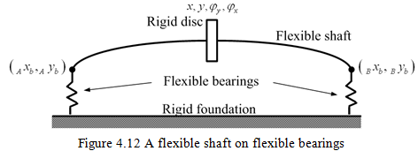
4.3 A Symmetrical Flexible Shaft on Anisotropic Bearings
For the present case, both the shaft and bearings are flexible as shown in Figure 4.12. All generalised coordinates are with respect to a fixed frame of reference and they are absolute displacements. The motion in two orthogonal planes will be considered simultaneously. The analysis allows finding different instantaneous displacements of the shaft at the disc and at bearings. The system will behave in a similar manner to that described in previous section, except that the flexibility of shaft will increase the overall flexibility of the support system as experienced by the rigid disc. An equivalent set of system stiffness and damping coefficients is first evaluated, which allows for the flexibility of the shaft in addition to that of bearings, and is used in place of bearing coefficients of the previous section analysis. The total deflection of the disc is the vector sum of the deflection of the disc relative to the shaft ends, plus that of shaft ends in bearings. For the disc, we observe the displacement of its geometrical centre.
The deflection of the shaft ends in bearings is related to the force transmitted through bearings by the bearing stiffness and damping coefficients as
| (4.35) |
where xb and yb are instantaneous displacements of shaft ends relative to bearings in the horizontal and vertical directions, respectively; and they take the following form
| (4.36) |
where Xb and Xb are complex displacements in x and y directions, respectively. Equation (4.36) can be differentiated once with respect to time, to give
| (4.37) |
It should be noted that bearings are modelled as a point connection with the shaft and only linear displacements is considered since they support mainly radial loads. Bearing forces have the following form
| (4.38) |
where Fbx and Fby are complex forces in x and y directions, respectively. On substituting in equation of motion (4.35), we get
| (4.39) |
and
| (4.40) |
which can be written in the matrix form for both bearings A and B, as
| (4.41) |
With
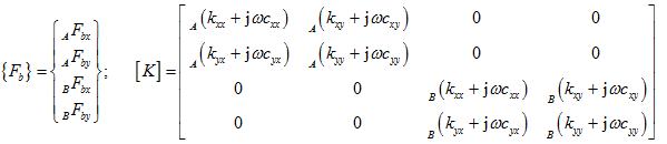
and
![]()
The magnitude of reaction forces transmitted by bearings can also be evaluated in terms of forces applied to the shaft by the disc.
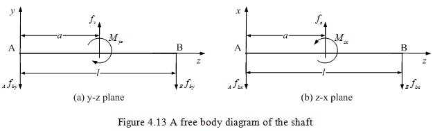
From Figure 4.13, the moment balance will be
| (4.42) |
and
| (4.43) |
Similarly, forces in the horizontal direction may be written as
| (4.44) |
and
| (4.45) |
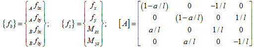
Equations (4.42)-(4.45) can be combined in a matrix form as
| (4.46) |
with
For the unbalance excitation, we have
| (4.47) |