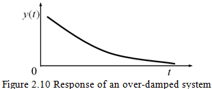
(ii) ![]() : Exponents of terms within the square bracket in equation (2.20) are real numbers, which means there would not be any harmonic functions. Hence, no oscillation is possible and it is called the over-damped system (see Figure 2.10).
: Exponents of terms within the square bracket in equation (2.20) are real numbers, which means there would not be any harmonic functions. Hence, no oscillation is possible and it is called the over-damped system (see Figure 2.10).
(iii) ![]() : Exponents of terms within the square bracket in equation (2.20) is a zero. The damping corresponding to this case is called the critical damping, cc, which is defined as
: Exponents of terms within the square bracket in equation (2.20) is a zero. The damping corresponding to this case is called the critical damping, cc, which is defined as
| (2.22) |
Any other damping can be expressed in terms of the critical damping by a non-dimensional number ![]() called the damping ratio, as
called the damping ratio, as
| (2.23) |
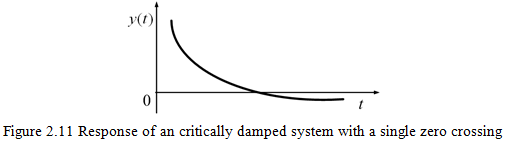
The solution for the critical damped case, having two real repeated roots, can be expressed as
| (2.24) |
For this case either no oscillation (similar to Fig. 2.10) or for specific initial conditions single crossing of the zero response axis is possible. Figure 2.11 shows a response of the critically damped system with a single crossing.
To summarize, depending upon the value of damping ratio ![]() (let us assume that it is a positive quantity) we can have following cases (i)
(let us assume that it is a positive quantity) we can have following cases (i) ![]() < 1: the under-damped condition with the damped natural frequency as
< 1: the under-damped condition with the damped natural frequency as ![]() , (ii)
, (ii) ![]() > 1: the over-damped condition, (iii)
> 1: the over-damped condition, (iii) ![]() = 1: the critical damping and (iv)
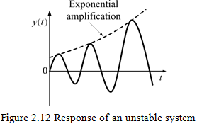
= 1: the critical damping and (iv) ![]() = 0: the undamped system. For all the three cases, the integration constants A and B are obtained from two initial conditions. Figure 2.12 shows a response of an unstable system with
= 0: the undamped system. For all the three cases, the integration constants A and B are obtained from two initial conditions. Figure 2.12 shows a response of an unstable system with ![]() < 0 (i.e., for the negative value of the damping) in which exponential increase in the amplitude can be seen. More detailed treatment of the present section could be seen in the text on basics of vibrations (Thomson and Dahleh, 1998).
< 0 (i.e., for the negative value of the damping) in which exponential increase in the amplitude can be seen. More detailed treatment of the present section could be seen in the text on basics of vibrations (Thomson and Dahleh, 1998).
2.3 Rankine Rotor Model
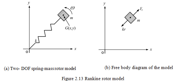
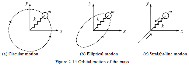
The single DOF rotor model has limitations that it cannot represent the orbital motion of the rotor in two transverse directions, which is the case in actual practice. Rankine (1869) used a two-DOF model to describe the motion of the rotor in two transverse directions as shown in Figure 2.13(a). The shape of orbit produced depends upon the relative amplitude and phase of the motions in two transverse directions (which in turn depend upon relative difference in stiffness in two transverse directions). The orbit could be a circular, elliptical or straight line, inclined to the x and y axes, as shown in Figure 2.14. The straight-line motion (Fig. 2.14c) could be considered as a single-DOF system described in Section 2.1, whereas, the elliptical orbital motion (Fig. 2.14b) may occur when the shaft has different stiffness in two orthogonal directions (along with cross-coupled stiffness terms).
The circular orbital motion (Fig. 2.14a) may occur for a symmetrical shaft. It can be thought as a mass attached with a spring and it revolves about a point. From the free body diagram of the rotor, as shown in Figure 2.13(b), for a constant spin speed the radius of whirling of the rotor centre will increase parabolically and is given as ![]() where Fc is the centrifugal force (= mω2R), R is the radius of path of the mass, and r is the extension of the spring of stiffness, k. It can be physically also visualized as there will not be any resonance condition, as it is found in the single DOF model, when the spin speed is increased gradually. This is a serious limitation of the Rankine model. Moreover, this model does not represent the realistic rotating unbalance force.
where Fc is the centrifugal force (= mω2R), R is the radius of path of the mass, and r is the extension of the spring of stiffness, k. It can be physically also visualized as there will not be any resonance condition, as it is found in the single DOF model, when the spin speed is increased gradually. This is a serious limitation of the Rankine model. Moreover, this model does not represent the realistic rotating unbalance force.