In previous chapter, a brief history and recent trends in the subject of rotor dynamics has been outlined. Apart from this, the main objective of the previous chapter was to have introduction of various phenomena in rotor dynamics so as to have an idea of them before detailed mathematical treatment is given to comprehensively understand these phenomena. It also briefed various mathematical methodologies, which are used to understand the dynamic behaviour of rotor systems, and summarized the recent and future requirements of the modern high-speed, high-power, and high-reliability rotating machineries.
Rotating machines are extensively used in diverse engineering applications, such as power stations, marine propulsion systems, aircraft engines, machine tools, automobiles, household accessories and futuristic micro- and nano-machines. The design trend of such systems in modern engineering is towards lower weight and operating at super critical speeds. An accurate prediction of rotor system dynamic characteristics is vitally important in the design of any type of machinery. There have been many studies relating to the field of rotor dynamic systems during the past years (Biezeno and Grammel, 1959; Dimentberg, 1961; Tondl, 1965; Rieger, 1977; Dimargonas and Paipetis, 1983; Mahrenholtz, 1984; Vance, 1988; Goodwin, 1989; Childs, 1993; Krämer, 1993; Lee, 1993; Rao, 1996; Lalanne and Ferraris, 1998; Genta, 1999; Rao, 2000; Admas, 2001; Yamamoto and Ishida, 2001; Robert, 2003; Muszynska, 2005; Genta, 2005; Chen and Gunter, 2005; Prabhu and Sekhar, 2008; Friswell et al., 2010). Of the many published works, the most extensive portion of the literature on rotor dynamics analysis is concerned with determining critical speeds, natural whirl frequencies, the frequency instability thresholds and bands (or regions), and the unbalance and transient responses. Apart from these analyses some works also cover balancing of rotors, the estimation of bearing dynamic parameters, the condition monitoring and the nonlinear response analysis.
For understanding basic phenomena of any dynamic system, it requires adequate modeling of the system. To start with, transverse vibrations of the rotor are considered in the present chapter. The torsional and axial vibrations will be considered in subsequent chapters. The dynamic system can be as simple as a single degree-of-freedom (DOF) system. The rotor is considered as a single mass in the form of a point mass, a rigid disc or a long rigid shaft. In a three-dimensional space a particle and a rigid body can have utmost three and six DOFs, respectively. On neglecting the torsional and axial vibrations effects, the single mass rotor has at most four DOF. In the present chapter, mathematical treatment is performed of simple rotor models in use over the years, e.g., the single-DOF undamped and damped model, the two-DOF Rankine’s model, the two and three-DOF Jeffcott rotor models, and four-DOF rotor models derived from the Jeffcott rotor model. . Various terminologies are introduced that are in use to explain the dynamic behaviour of the rotor system, e.g. the unbalance, the whirling and wobbling motions, the natural and excitation frequencies, the resonance, the critical speed, the synchronous, anti-synchronous and asynchronous motions, the forward and backward whirls, and the phase. The understanding of present chapter would help in exploring more complex rotor models described in subsequent chapters.
2.1 Single-DOF Undamped Rotor Model
The simplest model of the rotor system can be a single DOF. Figure 2.1 shows two types of rotor model. In Figure 2.1(a) the bearing (support) is assumed to be flexible and the rotor (the shaft and the disc) as rigid; whereas in Figure 2.1(b) the bearing is assumed to be rigid (i.e., the simply supported) and the shaft as flexible with the disc as rigid, where kb is the stiffness of each bearing, E is the modulus of elasticity or elastic modulus or Young’s modulus, ![]() with d is the diameter of the shaft, L is the span length of the shaft, and m is the mass of the disc.
with d is the diameter of the shaft, L is the span length of the shaft, and m is the mass of the disc.
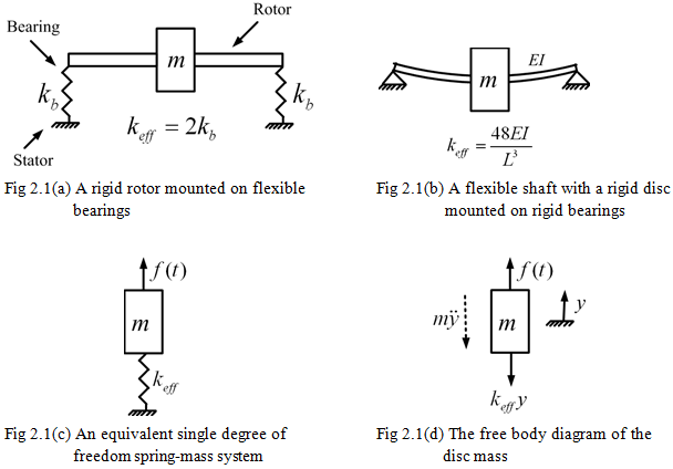
In both cases, the mass of the rotor is considered as that of the rigid disc that is mounted on the massless thin shaft. Both the cases can be idealized as a single DOF for transverse (lateral or bending) vibration of the rotor as shown in Figure 2.1(c), where keff is the effective stiffness of bearings or shaft as experienced by the disc mass and f(t) is external force on the disc mass (e.g., due to the unbalance). Here only linear transverse motion of the rotor is considered, simultaneous linear and tilting (angular) motions will be considered subsequently. Before considering the free-body diagram for derivation of governing equation and its solution, let us consider first the unbalance force and associated terminologies in more detail.