Example 2.1: A rotor has a mass of 10 kg and the operational speed of (100 ± 1) rad/s. What should be bounds of the effective stiffness of shaft so that the critical speed should not fall within 5% of operating speeds? Assume that there is no damping in the rotor system.
Solution:The operational speed range is 99 to 101 rad/s. Now 5% of the lower operational speed would be 99-99´0.05 = 94.05 rad/s, and 5% of the upper operational speed would be 101+101´0.05 = 106.05 rad/s.
Then the effective stiffness corresponding to the lower operating speed would be ω2nfm = 94.052 X 10 = 88.45 kN/m and the effective stiffness corresponding to the upper operating speed would be = 106.052 X 10 = 112.5 kN/m. Hence, the effective stiffness of shaft should not fall in the range of 98.1 to 112.5 kN/m. It should be noted that the unit of ωnf is in rad/s when other quantities are in SI units (i.e. m in kg and k in N/m).
Example 2.2: A rotor system has 100 rad/s as the critical speed and its operating speed is 120 rad/s. If we want to avoid altogether crossing of the critical speed, then what should be the enhancement in the support stiffness by an auxiliary support system. To avoid excessive vibration, let us assume we should have at least 5 rad/s of gap between the operating speed and the critical speed. The rotor has a mass of 10 kg.
Solution: The initial stiffness of the support is ω2nfm = 1002 X 10 = 100 kN/m.
First we can reach safely a rotor speed of 95 rad/s, which is 5 rad/s lower than the original critical speed of the rotor. Now since we cannot safely increase the rotor speed further, we need to increase the critical speed of the rotor to at least 125 rad/s. This will allow us to reach up to 120 rad/s that is 5 rad/s lower than 125 rad/s i.e. the new critical speed.
The corresponding effective of the support stiffness should be 1252 X 10 = 156.25 kN/m. Hence, the auxiliary support system should increase the effective stiffness by 56.25 kN/m.
Example 2.3: A 2 kg mass of a overhung rotor (cantilever) caused the deflection at the free end of 0.5 cm. What would be the stiffness and the natural frequency of the system?
(iii) Add damping to the system or the active control of the rotor: If a critical speed must be traversed slowly or repeatedly, or if machine operation near a critical speed cannot be avoided, then the most effective way to reduce the amplitude of vibration is to add the damping. On the other hand, some other form of the damping (e.g., the shaft material or hysteretic/internal damping, and squeeze-film damper) may lead to rotor instability (self-excited vibration).
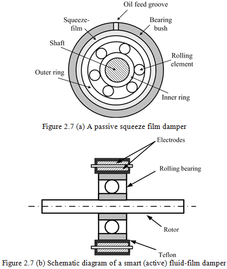
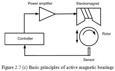
In recent years, advanced development of electromagnetic bearing technology has enabled the active control of rotor bearing systems. These bearings are called active magnetic bearings (AMB). In particular the electromagnetic suspension of a rotating shaft without the mechanical contact has allowed the development of supercritical shafts in conjunction with modern digital control strategies (Fig. 2.7c). With the development of smart fluids (for example electro and magneto-rheological fluids) now new controllable bearings are in the primitive development stage (Fig. 2.7b). The basic premise of such smart fluids is that their dynamic properties (i.e. the damping and the stiffness) can be controlled by changing the current or magnetic flux in a micro-second time. Schematics of typical passive and active (i.e., smart or controllable) squeeze film dampers, and active magnetic bearings are shown in Figure 2.7.