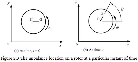
Figure 2.3 shows positive conventions and variables to define the unbalance location on a rotor system at a particular instant of time, t. For a constant angular velocity of the rotor, ω, the location of the unbalance is given as θ = ωt. In general θ ≠ ω (the ‘dot’ represents the derivative with respect to the time), i.e., when a rotor has some angular acceleration, e.g., for a constant angular acceleration ![]() and for zero initial conditions, we will have
and for zero initial conditions, we will have ![]() .
.
2.1.2 Equation of Motion: On application of the Newton’s second law of motion on the free body of the rotor mass as shown in Figure 2.1(d), i.e., on equating the sum of external forces to the mass of rotor multiplied by the acceleration of center of gravity of the rotor mass (here it is assumed that centrifugal force is acting as an external force, hence, the centre of gravity could be assumed at centre of rotation of the disc C itself. Subsequently, we would see that the centrigul ), we have
| (2.4) |
where keff is the effective stiffness of the rotor system (see Figure 2.1) and keffy is the restoring force that acts opposite to the motion so negative sign. Equation (2.4) is a standard form of equation of motion of a single DOF spring-mass system and could be rearranged as
| (2.5) |
2.1.3 Free Vibrations: From the free vibration, when the external unbalance force is absent (i.e., e = 0), it is generally assumed that the rotor mass will have a simple harmonic oscillation and the free response displacement is expressed as
| (2.6) |
where ωnf is the frequency of oscillation during the free vibration and it is called the natural frequency of the system. On substituting equation (2.6) (with ![]() ) into the homogeneous part (i.e., with e = 0) of equation of motion (2.5), it gives
) into the homogeneous part (i.e., with e = 0) of equation of motion (2.5), it gives
| (2.7) |
For a non-trivial solution (i.e., Y ≠ 0 or ωnf ≠ 0) of equation (2.7), the frequency equation (or natural frequency) of the system can be written as
| (2.8) |
In which the negative sign has no physical meaning since the frequency cannot be negative quantity.
2.1.4 Forced responses: Now to obtain the steady state forced response, it can be expressed as
| (2.9) |
where Y is the amplitude of displacement, ω is the spin speed of the rotor, and Φ is the phase lag of displacement with respect to the unbalance force (normally in absence of damping the phase will be zero). On substituting equation (2.9) (noting ![]() )with into equation (2.5), the steady state forced response amplitude can be obtained as
)with into equation (2.5), the steady state forced response amplitude can be obtained as
![]()
On expanding, we get
![]()
On separating the sine and cosine terms of ωt, we have
![]()
which gives
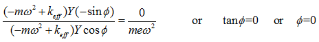
And hence

or
| (2.10) |
where ![]() is the non-dimensional unbalance response (ratio of the unbalance response to the eccentricity) and
is the non-dimensional unbalance response (ratio of the unbalance response to the eccentricity) and ![]() is the frequency ratio (ratio of the spin speed of the rotor to the natural frequency of the rotor system). The absolute value of non-dimensional unbalance response,
is the frequency ratio (ratio of the spin speed of the rotor to the natural frequency of the rotor system). The absolute value of non-dimensional unbalance response, ![]() , is plotted with respect to the frequency ratio as shown in Figure 2.4. From Figure 2.4 and equation (2.10) it should be noted that we have unbounded unbalance response when the denominator
, is plotted with respect to the frequency ratio as shown in Figure 2.4. From Figure 2.4 and equation (2.10) it should be noted that we have unbounded unbalance response when the denominator ![]() becomes zero, i.e., when the spin speed is
becomes zero, i.e., when the spin speed is
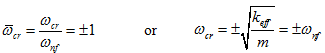 |
(2.11) |