This is a resonance condition and the spin speed corresponding to the resonance is defined as the critical speed. The subscript: cr represents the critical. For the present case, the critical speed is equal to the transverse natural frequency of the non-rotating rotor system as given by equation (2.11). The undamped steady-state forced response amplitude tends to be infinity at the critical speed. The natural frequency and the critical speed concepts have come from the free and forced vibrations, respectively. It should be noted that in rotor dynamics, in general, the natural frequency might not be a constant and might vary with the spin speed of the shaft (e.g., when the gyroscopic couple is considered in the analysis especially when the spin speed of rotor is high, for the case of speed dependent bearing dynamic properties, etc.). The ± sign represent that the rotor will have critical speed while rotating in either the clockwise or counter clockwise sense (earlier we noted that the natural frequency is always positive, however, the spin speed of the rotor can be described as positive or negative depending upon its sense of rotation). Since the damping is not considered in the analysis the phase angle, Φ, remains zero before critical speed (or 180° after the critical speed, however, its value at the critical speed is 90°).
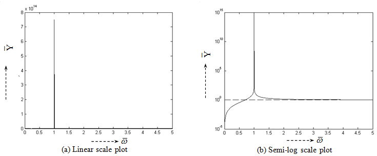
Figure 2.4 Variation of the absolute non-dimensional unbalance response versus the frequency ratio
In Fig. 2.4 the response changes its sign (i.e., the positive to the negative) after the frequency ratio equal to unity, which corresponds to the critical speed (i.e., the spin speed of the shaft is equal to the natural frequency of the rotor system). It means that the phase difference between the force and the response becomes 180°, which is 0° when the frequency ratio is less than unity, in the absence of damping. Both the linear and semi-log plots are shown to have clarity of the response variation, near and away from the critical speed. It can be seen that as the frequency ratio increases above unity the non-dimensional response asymptotically approaches to unity, which means unbalance response approaches to the eccentricity of the rotor. Physically it implies that the rotor rotates about its center of gravity at high frequency ratio and not the actual centre of rotation. This means for e = 0, we should not have any whirling and only the spinning of the shaft would be observed.
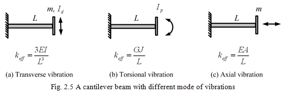
The analysis presented in this section can be applied to the transverse, torsional and axial vibrations of rotors (see Fig. 2.5) and accordingly natural frequency can be termed by prefixing respective types of vibrations. For torsional vibrations (Fig. 2.5b) care should be taken that the mass will be replaced by the polar mass moment of inertia of the rotor and the stiffness will be by the torsional stiffness (G is the shear modulus or modulus of elasticity in shear or modulus of rigidity, ![]() with d is the diameter of the shaft). Similarly, for the axial vibrations (Fig. 2.5c) the mass will remain the same as transverse vibrations; however, the stiffness will be the axial stiffness. More detailed treatment will be presented in subsequent chapters.
with d is the diameter of the shaft). Similarly, for the axial vibrations (Fig. 2.5c) the mass will remain the same as transverse vibrations; however, the stiffness will be the axial stiffness. More detailed treatment will be presented in subsequent chapters.
2.1.5: Attenuation of Vibrations: The most common cause of the vibrations in rotors is the unbalance among the other faults and it will always be present in a rotor. However, the unbalance response can be reduced up to a desired level depending upon applications by one or combination of following three methods.
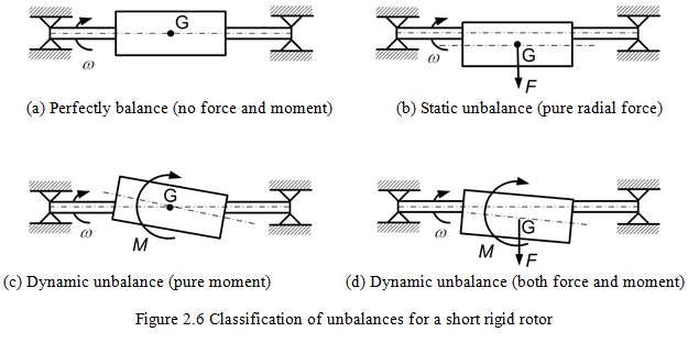
(i) Correction at the source: Balancing the rotor is the most direct approach, since it attacks the problem at source. However, in practice a rotor cannot be balanced perfectly (Fig. 2.6a) and the best achievable state of balance tends to degrade during operation of a rotor (e.g., in the turbo-machinery).
There are two types of unbalances in rigid rotors (a) the static unbalance: The principal axis of the polar mass moment of inertia of the rotor is parallel to the centerline of the shaft as shown in Figure 2.6b. The rotor can be balanced by a single plane balancing and (b) the dynamic unbalance: The principal axis of the polar mass moment of inertia of the rotor is inclined to the centerline of the shaft as shown in Figure 2.6c and d. For balancing such (rigid) rotors, minimum of two balancing planes are required. The balancing of rotors would be covered in more detail in Chapter 13.
(ii) Operate the rotor away from the critical speed: This could be done during the design itself, or during operation by providing an auxiliary support.At the design stage the critical speed can be altered by changing the rotor mass and its distributions, and the effective stiffness (e.g., by changing dimensions of the shaft, i.e., the shaft diameter and length; the location and type of bearings, etc.). During the operation an auxiliary support can be provided to increase the effective stiffness of the rotor, which in turn increases the critical speed. For the case when the rated operational speed is above the critical speed, the actual rotor critical speed can be safely traversed by this arrangement (by temporarily increasing the critical speed) and then the auxiliary support can be withdrawn which brings the critical speed of the rotor again below the rated operation speed (refer Example 2.2). Another way to traverse the critical speed is to accelerate the rotor spin speed very quickly to reach the operating speed which is well above the critical speed of the rotor. In general, changing the critical speed is useful for machines with a constant or with a narrow range of operational speed (e.g. the turbo-machinery in power plants).