Vibrations caused by the misalignment tend to peak near the machine critical speed, but away from the critical may either stay about constant or tend to increase, in many cases they have been reported to appear suddenly as machine speed is increased, and to disappear equally quickly for a particular speed range. For moderate misalignment the shaft amplitude is reduced in the sense of the applied pre-load, so that if it were originally circular it might become elliptical; that is because there is more resistance to motion in the direction opposing the preload so the rotor ‘feels’ a higher support stiffness in this direction. For more severe cases the orbit may become banana-shaped or figure-8 shaped (Figure 15.7). If the misalignment has been introduced when two shafts were improperly coupled, some reduction of the undesirable symptoms may be obtained by using a flexible coupling; the amount of improvement obtained will depend upon the coupling stiffness. Bearing temperature and oil-film pressure are other indirect methods of detecting misalignment. Coupling alignment may be checked by taking dial gauge readings and gap measurements (Piotrowski, 1986). The variations in these measurements should be recorded as both shafts rotated simultaneously, and averaged values are used to calculate the misalignment present. The alignment of bearings may be checked using optical/laser methods (one bearing with another) or using feeler gauges in the clearance between journal and bush. Also the proximity transducer measurement may be used to record the gap between the shaft and each end of a bearing and so indicate alignment. Other indirect indicators of alignment in fluid bearings are measurements of the bearing temperature and lubricant pressure distribution.
The misalignment of machinery shafts causes reaction forces to be generated in the coupling which affect the machines and are often a major cause of machinery vibration. Bloch (1976) identified the forces and moments developed by a misaligned gear coupling. Gibbons (1976) showed that these forces and moments are developed by different types of misaligned couplings. Comparative values of these forces were presented. The effect that these forces upon the machines has been described in general terms. Schwerdlin (1979) found that the manufacturers published ratings for flexible couplings typically do not take into account reaction forces from misalignment, speed, and torque. In general, these forces must be determined by tests in order to reveal their influence on bearings, shafts and other components in the drive. Shekhar and Prabhu (1995) modeled the rotor-bearing system using higher-order finite elements by considering deflection, slope, shear force, bending moment with eight DOFs per node. The reaction forces and moments developed due to flexible coupling misalignment were derived and introduced in the model. The unbalance response in two harmonics was evaluated. The increase in harmonics with misalignment was modeled by using FEM analysis. The location of the coupling with respect to the bending mode shape had a strong influence on the vibrations. The bending 1 x vibration response showed that coupling misalignment did not significantly alter the amplitude. The 2 x vibration response showed the characteristic signature of misaligned shafts. The theoretical model for the coupling-rotor-ball bearing systems with misalignment was derived by Lee and Lee (1999), including the loads and deformations of the bearings as well as the flexible coupling as the misalignment effects. Throughout the extensive experimental and simulation works, the model was validated and the rotor dynamic characteristics related to misalignment were investigated.
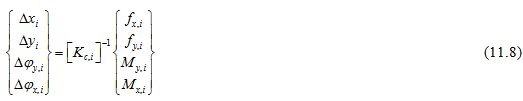
Prabhakar et al. (2002) used the finite element method (FEM) for transient analysis with crack and coupling misalignment separately for the same rotor to distinguish the crack from the coupling misalignment. Continuous wavelet transform (CWT) was used to extract characteristic features from vibration response of these two flaws in the rotor system. A method to estimate both the rotor unbalance (amplitude and phase) and the misalignment of a rotor–bearing–foundation system was presented by Sinha et al. (2004). The estimation uses a priori rotor and bearing models along with measured vibration data at the bearing pedestals from a single rundown or run-up of the machine. The method also estimates the frequency-band-dependent foundation parameters to account for the dynamics of the foundation. The suggested method was applied to a small experimental rig and the estimated results were validated. It assumed that the rotor misalignment occurs at the couplings between the multi-rotors. The nature of the rotor misalignment could be parallel, angular or combined as shown in Fig. 15.4, but all of them would generate forces and/or moments. The method estimated the forces and moments due to the rotor misalignment. However, they considered displacements and angles rather than forces and moments, although this required the stiffness matrix of the coupling. Suppose that the stiffness of the i th coupling is ![]() ; then the linear misalignment,
; then the linear misalignment,![]() ; and the angular misalignment,
; and the angular misalignment,![]() ; at the i th coupling in the horizontal and vertical directions may be calculated as
; at the i th coupling in the horizontal and vertical directions may be calculated as
Pennacchi and Vania (2005) focused on the application of two different diagnostic techniques aimed to identify the most important faults in rotating machinery as well as on the simulation and prediction of the frequency response of rotating machines. The application of the two diagnostics techniques, the orbit shape analysis and the model based identification in the frequency domain, was described by means of an experimental case study that concerns a gas turbine-generator unit of a small power plant whose rotor-train was affected by an angular misalignment in a flexible coupling, caused by a wrong machine assembling. The fault type was identified by means of the orbit shape analysis, and then the equivalent bending moments, which enabled the shaft experimental vibrations to be simulated, were identified using a model based identification method. These excitations were used to predict the machine vibrations in a large rotating speed range inside which no monitoring data were available. The results obtained emphasize the usefulness of integrating common condition monitoring techniques with diagnostic strategies.
15.4 Rubs
Rubs are produced when the rotating shaft comes into contact with the stationary components of the machine. Rubs are said to be accompanied by a great deal of high-frequency spectral activities. A rub is generally a transitory phenomenon. The rub may typically be caused by the mass unbalance, turbine or compressor blade failure, defective bearings and/or seals, or by rotor misalignment, either thermal or mechanical. Several different physical events may occur during a period of contact between the rotor and the stator: initial impacting stage, frictional behaviour between the two contacting parts and an increase in the stiffness of the rotating system whilst contact is maintained, to name just three. The behaviour of the system during this period is highly non-linear and may be chaotic.
The rotor-to-stator rub is one of the malfunctions occurring often in rotating machinery. It is usually a secondary phenomenon resulting from other faults. When the rub occurs, the partial rub can be observed at first. During one complete period, rotor and stator have rub and impact interaction once or a fewer times. Alternately changed stress is formed in the shaft and the system can exhibit complicated vibration phenomena. Chaotic vibration can be found under some circumstances. Gradual aggravation of the partial rub will lead to full rub and severe vibration makes the normal operation of the machine impossible. Mathematically, the rotor system with rotor-to-stator rub is a nonlinear vibrating system with piecewise linear stiffness. There have been many publications on this problem and relevant topics.
Rubs may be classified as partial rubs or full rubs or may take the form of a stick-slip action. A partial rub is that where contact between the shaft and stationary component exists only for part of the cycle time, for example the high spot on a shaft rubs against part of a seal, or a bowed rotor rubs the stator. A flattened waveform and orbit are strong indications of a partial rub. The frequency spectra for a partial rub always show some synchronous vibration (1 x shaft rotational shaft) together with some sub-harmonics which are related to free lateral vibrations of the rotor. The sub-harmonics may be in either the forward or backward directions.