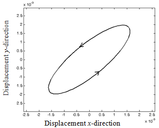
Fig. 15.3(a) Orbit plot for rotor spin speed of 200 rpm (below the first critical speed)
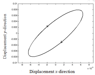
Fig. 15.3(b) Orbit plot for rotor speed of 400 rpm (between the first and second critical speed)
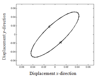
Fig. 15.3(b) Orbit plot for rotor speed of 1000 rpm (above the second critical speed)
The unbalance vibration occurs at machine rotational frequency, in general, but sometimes higher-harmonics of rotational speed are excited. Machine vibration caused by unbalance can mostly be detected by monitoring shaft displacement amplitude and phase as the machine is run through its critical speed, filtering out non-rotational speed frequencies by using tracking filter. The amplitude peaks at the critical speed, and phase changes by 1800 passing through about 900 at the critical and it can be seen in the Bode plot (see Figure 15.1-15.2). The shaft whirl orbit takes (generally) on an orbit (or trajectory) shape (unless the shaft support impedance in isotropic, in which case it is circular), the direction of the ellipse changes as the critical speed is passed through (see Figure 15.3).
Answer.
Already balancing of rotors (a systematic approach for quantifying the unbalance) has been covered in great details in Chapter 13, which must be performed after every major overhauling of the machinery. A review of the research work performed in real-time active balancing and active vibration control for rotating machinery, as well as the research work on dynamic modeling and analysis techniques of rotor systems, is presented by Zhou and Shi (2001). The basic methodology and a brief assessment of major difficulties and future research needs are also provided.
In some instances the magnitude and phase of the unbalance vibration vector might change with time. When symptoms of unbalance exhibit this feature the correct treatment is not normally to simply re-balance the machine. Example of fault in some categories are (i) the heavy spot on the shaft causing a thermal bow, it occurs when the heavy rotors of turbine are left non-rotated for cooling during shutdown and due to heavy sag it get permanent bent configuration or even when the rotor has axial asymmetry of the thermal distribution (ii) components mounted loosely on the shaft e.g. discs, gears, flywheel, etc.; and (iii) moisture entering a hollow shaft, which vary in amount and location during the operation of the machinery.