15.2 Shaft Bow or Thermal Bow
The phenomenon of shaft forcing due to an initial bow (or bend) has aroused interest over the last four decades years or so, albeit much less than mass unbalance. Bows in shafts may be caused in several ways, for example due to creep, thermal distortion or a previous large unbalance force. The forcing caused by a shaft bow is similar, though slightly different, to that caused by conventional mass unbalance. There have been numerous cases in industry where vibration has been assumed to have arisen from mass unbalance and rotors have been balanced using traditional balancing procedures. This has repeatedly left engineers puzzled as to why vibration persists after balancing, and vibration levels may indeed even be worse than before balancing took place.
One of the typical reasons for an unbalance in a rotor is due to warping or static bending (permanent or temporary). Such rotors are called warped or bowed rotors and are encountered in practice for different reasons, e.g., allowing a horizontal rotor rest for long period time or due to rubbing of a shaft on a seal. Though the effect of a bent is similar to unbalance conditions, it is different from the classical eccentricity of the mass from the geometric centre. The bow and the eccentricity are in general in different angular locations and the warped rotor behaves somewhat differently from purely unbalance rotors. In important investigation of such rotor is performed by Nicholas et al. (1976), Ehrich (1992) and Rao (2001) both analysis and diagnostics point of view. The bowed shaft response is independent of shaft speed and causes different amplitude and phase angle relationships than is found with ordinary mass unbalance, where the forcing is proportional to the square of the speed Nicholas et al. (1976). In the case of a bowed rotor, the excitation is proportional to the magnitude of the bow along the rotor. A bowed rotor gives rise to synchronous excitation, as with mass unbalance, and the relative phase between the bend and the unbalance causes different changes of phase angle through resonance than would be seen in the pure unbalance case, as described in references Nicholas et al. (1976).
It is therefore important to be able to diagnose a bow in a rotor from vibration measurements and thus distinguish between it and mass unbalance. The identification method was extended to include the identification of a bend in a rotor, as well as estimating the unbalance and flexible support parameters of the rotor-bearings-foundation system by Edwards et al. (2000). They expressed the rotor bow in terms of the free-free eigenvectors of the rotor, which are readily obtained from the numerical model. It is considered that, even for relatively simple systems with low numbers of modes, these modes will still be sufficient to adequately represent complicated shaft bow geometry. The force due to the bow is then expressed in terms of shaft stiffness and bow geometry, which contain the unknown modal coefficients to be estimated during the process of identification.
A Fault Model: The effects of most typical faults of rotating machines can be simulated by means of suitable sets of equivalent excitations, forces or moments, that are applied to nodes of the finite element model of the shaft-train. When beam finite elements are used, each node of the beam elements has four-DOF: two orthogonal radial displacements (lateral vibrations) and rotations (associated with a shaft bending in two orthogonal planes). The equivalent excitations are referred to an absolute reference system and are denoted ![]() This vector can be written as (Pennacchi and Vania, 2004)
This vector can be written as (Pennacchi and Vania, 2004)
|
(11.1) |
Depending on the type of fault the equivalent excitations can be expressed by a rotating vector, with a certain harmonic content, or by a fixed vector. In general, in the absence of nonlinear effects, the frequency spectrum of the equivalent excitations contains significant harmonic components limited to the rotating frequency (1×) and to integer multiples of this frequency (i.e. 2×, 3×).
Shaft Bow Model: A bowed rotor or a permanent bent rotor can be considered as the Jeffcott rotor model with a static deflection from the bearing centre line with a magnitude of ![]() at a phase angle
at a phase angle ![]() with the unbalance as the reference line. This gives the equation of motion of the following form (Rao, 2001)
with the unbalance as the reference line. This gives the equation of motion of the following form (Rao, 2001)
|
(11.2) |
where m, c and k are mass, damping and stiffness of the rotor system, , the whirl radius is defined as ![]() , x and y are displacements of the disc mass in the horizontal and vertical directions, respectively. Force components consist of two parts, the first due to the rotor unbalance
, x and y are displacements of the disc mass in the horizontal and vertical directions, respectively. Force components consist of two parts, the first due to the rotor unbalance![]() and the second due to rotor bow
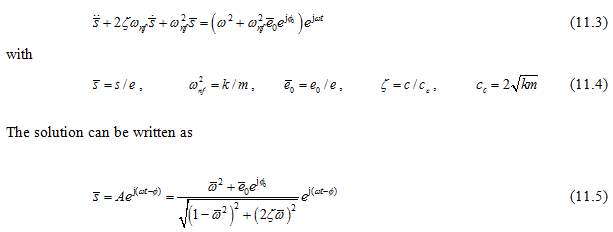
and the second due to rotor bow ![]() . On dividing by me, equation (11.2) can be written as
. On dividing by me, equation (11.2) can be written as