where ![]() is the complex displacement with respect to the unbalance force. It should be noted that the phase reference is the unbalance location. Hence, the amplitude of the unbalance response and the bow response amplitudes, respectively, are
is the complex displacement with respect to the unbalance force. It should be noted that the phase reference is the unbalance location. Hence, the amplitude of the unbalance response and the bow response amplitudes, respectively, are
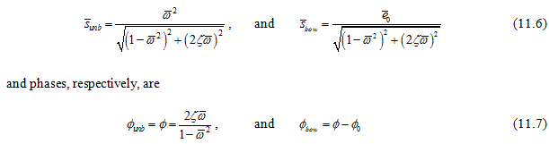
Hence, the effect of bow would be to give the same frequency as that of the spin speed of the shaft, however, it may change the unbalance response and its phase depending upon the phase of the bow.
15.3 Misalignment
Unbalance and misalignment are the two most common source of machinery vibration. The objective of the alignment is to have two coupled shafts perfectly collinear under operating conditions or between the bearing and the shaft their axis should be co-linear or two bearings carrying a common shaft should have their axis collinear. Accordingly, misalignments can be classified as (i) parallel (ii) angular, and (iii) combination of parallel and angular misalignments (Fig. 15.4). Like the unbalance, the misalignment is an installation and subsequent maintenance problems, since it can be corrected and prevented by using the proper installation and maintenance procedures. Shafts with a heavy pre-load carried by the bearings (e.g., in angular contact ball bearings in tandem, the preloading must be applied to keep the bearing in assembled position), as distinct from the out-of-balance load, can show variation characteristics similar to those caused by bearing misalignment (Figure 15.6). This category of fault is probably the second most common cause of machine vibration, after the unbalance. A pre-load might also be applied at a bearing as a consequence of gear-mesh forces, aerodynamic forces and hydrodynamic forces. Misalignment may be present because of improper machine assembly or as a consequence of thermal distortion, and it results in additional loads being applied to the bearing.
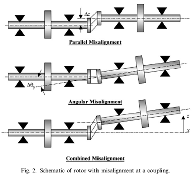
Fig 15.4 Schematic of rotor with misalignment at a coupling (Sinha et al., 2004)
The general perception and observation is that misalignment in multi-coupled rotors generates a 2x (twice the rotating speed) component in the response of the machine (Dewell and Mitchell, 1984; Ehrich, 1992) and the effect on the 1x component is assumed to be small. However, Jordan (1993) confirms that the misalignment initially affects the 1x response resulting in an elliptical orbit, but in the case of severe misalignment the orbit plot may look like a figure eight due to the appearance of a 2x component in the response. These features are usually used for the detection of the presence of rotor misalignment (Jordan, 1993). In practice both the 1x and the 2x response will be affected by misalignment, and the physical source of these effects may be modelled as a rotor bend and rotor asymmetry, respectively.
The misalignment of adjoining shafts, or of the bearings of one shafts, causes abnormal loads to be transmitted through the bearings, and imposes additional bending stress on the shaft thereby reducing its fatigue life. In some cases misalignment may cause one bearing to be unloaded (if the pre-load so applied is in the opposite direction to the normal gravity loads, this can result in lowering the machine critical speed or even instability in the system. These symptoms are sometimes present in addition to that of excessive vibration. The vibration associated with misalignment occurs at 1x machine running speed but, unlike unbalance case, there is usually a substantial component in the axial direction, which may be greater than radial direction. Substantial amounts of misalignment (or the pre-load) can also cause vibrations at frequencies of 2xmachine running speed, and sometimes higher multiplies. When the amplitude at twice the machine running speed exceeds 150 percent of the amplitude at running frequency, the misalignment is producing a severe action at coupling.
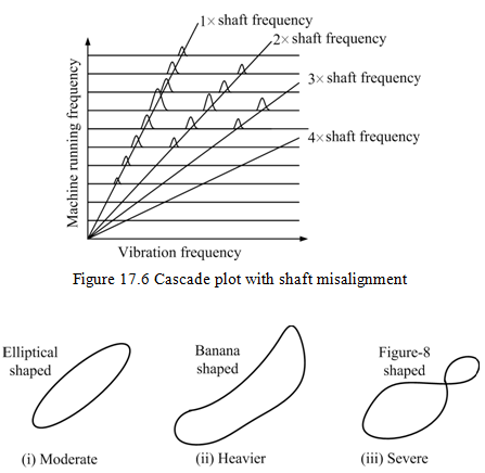
Figure 15.7 Lissajous plot for different level of misalignment