From equation 47 and equation 53 the ratio V0 /Vin is obtained as
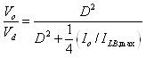 (54)
(54)
In Figure 11 the step down characteristics in continuous and discontinuous modes of operation is shown. In this figure the voltage ratio ( V0 /Vin) is plotted as a function of Io / ILB,maxfor various duty ratios using equation 32 and equation 54. The boundary between the continuous and the discontinuous mode, shown by dashed line in Figure 11, is obtained using equation 32 and equation 48 .
Discontinuous-Conduction Mode with Constant V0
In some applications such as regulated dc power supplies, Vin may vary but V0 is kept constant by adjusting the duty ratio. From equation 44 the average inductor current at the boundary of continuous conduction is obtained as
![]() (56)
(56)
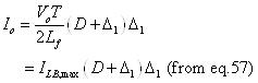
From equation 56 it can be seen that, for a given value of V0 the maximum value of ILB occurs at D=0 and is given by
![]() (57)
(57)
From equation 56 and equation 57 the relation between ILB and ILB,max is
![]() (58)
(58)
From equation 52 , the output current is obtained as
 (59)
(59)
Solving the equation 59 for ![]() and substituting its value in equation 47 gives
and substituting its value in equation 47 gives
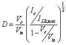 (60)
(60)