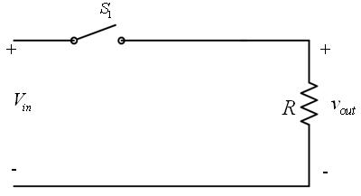
Principle of Step Down Operation
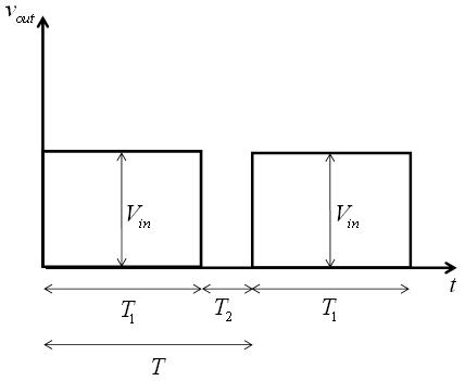
The principle of step down operation of DC-DC converter is explained using the circuit shown in Figure 3a . When the switch S1 is closed for time duration T1, the input voltage Vin appears across the load. For the time duration T2 is switch S1 remains open and the voltage across the load is zero. The waveforms of the output voltage across the load are shown in Figure 3b .
|
|
Figure 3a: Step down operation |
Figure 3b: Voltage across the load resistance |
The average output voltage is given by
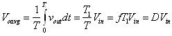 (1)
(1)
The average load current is given by
![]() (2)
(2)
Where
T is the chopping period
![]() is the duty cycle
is the duty cycle
f is the chopping frequency
The rms value of the output voltage is given by
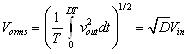 (3)
(3)
In case the converter is assumed to be lossless, the input power to the converter will be equal to the output power. Hence, the input power ( Pin) is given by
![]() (4)
(4)
The effective resistance seen by the source is (using equation 2)
![]() (5)
(5)
The duty cycle D can be varied from 0 to 1 by varying T1, T or f. Thus, the output voltage Voarg can be varied from 0 to Vin by controlling D and eventually the power flow can be controlled.