Determination of I1 and I2
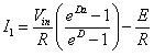
At the end of mode 2 the load current becomes
![]() (13)
(13)
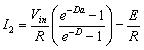
At the end of mode 2 , the converter enters mode 1 again. Hence, the initial value of current in mode 1 is
![]() (14)
(14)
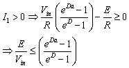
From equation 8 and equation 12 the following relation between I1 and I2 is obtained as
![]() (15)
(15)
![]() (16)
(16)
Solving equation 15 and equation 16 for I1 and I2 gives
 (17)
(17)
 (18)
(18)
Where
![]() (19)
(19)
where f is the chopping frequency.
Current Ripple
The peak to peak current ripple is given by
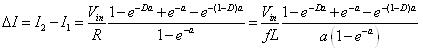 (20a)
(20a)
In case fL >>R,a → 0 . Hence, for the limit a → 0 equation 20 becomes
![]() (20b)
(20b)
To determine the maximum current ripple ( ![]() ), the equation 20a is differentiated w.r.t. D . The value of
), the equation 20a is differentiated w.r.t. D . The value of ![]() is given by
is given by
![]() (21)
(21)
For the condition 4 fL >>R,
![]() (22)
(22)
Hence, the maximum torque ripple is given by
![]() (23)
(23)
If equation 20b is used to determine the maximum current ripple, the same result is obtained.
Continuous and Discontinuous Conduction Modes
In case of large off time, particularly at low switching frequencies, the load current may be discontinuous, i.e. ![]() will be zero. The necessary condition to ensure continuous conduction is given by
will be zero. The necessary condition to ensure continuous conduction is given by
 (24)
(24)