Discontinuous Conduction Mode with ConstantInput Voltage Vin
In applications such as speed control of DC motors, the input voltage (Vin) remains constant and the output voltage (V0) is controlled by varying the duty ratio D. Since V0 = DVin, the average inductor current at the edge of continuous conduction mode is obtained from equation 43 as
![]() (44)
(44)
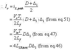
In Figure 9 the plot of ILB as a function of D , keeping all other parameters constant, is shown. The output current required for a continuous conduction mode is maximum at D = 0.5 and by substituting this value of duty ration in equation 44 the maximum current ( ILB,max) is obtained as
![]() (45)
(45)
From equation 44 and equation 45 , the relation between ILB and ILB,max is obtained as
![]() (46)
(46)
To understand the ratio of output voltage to input voltage (V0 /Vin) in the discontinuous mode, it is assumed that initially the converter is operating at the edge of the continuous conduction (Figure 7), for given values of T,L,Vd and D. Keeping these parameters constant, if the load power is decreased (i.e., the load resistance is increased), then the average inductor current will decrease. As is shown in Figure 10 , this dictates a higher value of V0 than before and results in a discontinuous inductor current.
|
|
Figure 10: Discontinuous operation is buck converter |
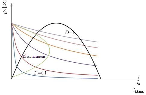
Figure 11: Buck converter characteristics for constant input current |
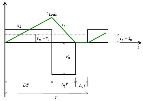
In the time interval ![]() the current in the inductor Lf is zero and the power to the load resistance is supplied by the filter capacitor alone. The inductor voltage eL during this time interval is zero. The integral of the inductor voltage over one time period is zero and in this case is given by
the current in the inductor Lf is zero and the power to the load resistance is supplied by the filter capacitor alone. The inductor voltage eL during this time interval is zero. The integral of the inductor voltage over one time period is zero and in this case is given by
![]() (47)
(47)
In the interval ![]() ( Figure 10 ) the current ripple in Lf is
( Figure 10 ) the current ripple in Lf is
![]() (48)
(48)
From Figure 10 is can be seen that
![]() (since the current falls) (49)
(since the current falls) (49)
![]() (50)
(50)
Substituting the values of ![]() and eL from euqation 49 and equation 50 into equation 48 gives
and eL from euqation 49 and equation 50 into equation 48 gives
 (51)
(51)
 (52)
(52)
Hence, ![]() (53)
(53)