The Buck Converter With RLE Load
The buck converter is a voltage step down and current step up converter. The two modes in steady state operations are:
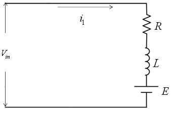
Mode 1 Operation
In this mode the switch S1 is turned on and the diode D1 is reversed biased, the current flows through the load. The time domain circuit is shown in Figure. The load current, in S domain, for mode 1 can be found from
![]() (6)
(6)
Where
I01 is the initial value of the current and I01 = I1.
|
|
Figure 4: Time domain circuit of buck converter in mode 1 |
Figure 5: Time domain circuit of buck converter in mode 2 |
From equation 6 , the current i1(s) is given by
![]() (7)
(7)
In time domain the solution of equation 7 is given by
![]() (8)
(8)
The mode1 is valid for the time duration ![]() . At the end of this mode, the load current becomes
. At the end of this mode, the load current becomes
![]() (9)
(9)
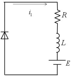
Mode 2 Operation
In this mode the switch S1 is turned off and the diode D1 is forward biased. The time domain circuit are shown in Figure 5 . The load current, in S domain, can be found from
![]() (10)
(10)
Where
I02 is the initial value of load current.
The current at the end of mode1 is equal to the current at the beginning of mode 2 . Hence, from equation 9 I02 is obtained as
I02 = I2 (11)
Hence, the load current is time domain is obtained from equation 10 as
![]() (12)
(12)