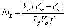
From equation 27 and equation 30 the following relation is obtained for the current ripple
![]() (31)
(31)
Hence, from equation 31 the relation between input and output voltage is obtained as
![]() (32)
(32)
If the converter is assumed to be lossless, then
![]() (33)
(33)
The switching period T can be expressed as
![]() (34)
(34)
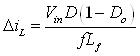
From equation 34 the current ripple is given by
 (35)
(35)
Substituting the value of V0 from equation 32 into equation 35 gives
 (36)
(36)
Using the Kirchhoff's current law, the inductor current iL is expressed as
![]() (37)
(37)
If the ripple in load current ( i0 ) is assumed to be small and negligible, then
![]() (38)
(38)
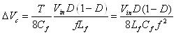
The incremental voltage ![]() across the capacitor (Cf) is associated with incremental charge
across the capacitor (Cf) is associated with incremental charge ![]() by the relation
by the relation
 (39)
(39)
The area of each of the isoceles triangles representing ![]() in Figure 7 is given by
in Figure 7 is given by
![]() (40)
(40)
Combining equation 39 and equation 40 gives
![]() (41)
(41)
Substituting the value of ![]() from equation 31 into equation 41 gives
from equation 31 into equation 41 gives
 (42)
(42)
Boundary between Continuous and Discontinuous Conduction
The inductor ( iL) and the voltage drop across the inductor ( eL ) are shown in Figure 8 .
|
|
Figure 8: The inductor voltage and current waveforms for discontinuous operation |
Figure 9: Current versus duty ratio keeping input voltage constant. |
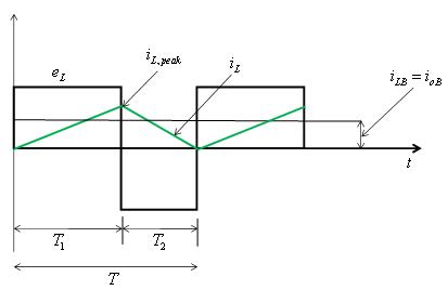
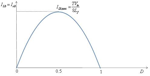
Being at the boundary between the continuous and the discontinuous mode, the inductor current iL goes to zero at the end of the off period. At this boundary, the average inductor current is (B rferes to the boundary)
![]() (43)
(43)
Hence, during an operating condition, if the average output current (IL) becomes less than ILB, then IL will become discontinuous.