Now, ![]() is propagated through gate-4, making D-frontier comprise gate-5. Propagation of
is propagated through gate-4, making D-frontier comprise gate-5. Propagation of ![]() through gate-4 implies net g =0 by backward implication; also gate-2 now falls in J-frontier. These changes are illustrated in Figure 7(k).
through gate-4 implies net g =0 by backward implication; also gate-2 now falls in J-frontier. These changes are illustrated in Figure 7(k).
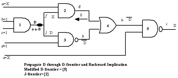 Figure 7(k): Propagation of
 ![]() , implications and D and J-frontier changes
, implications and D and J-frontier changes
In the next step, backward implication of the gate at J-frontier (gate-2) has two choices (i) a =X, f =0, (ii) a =0, f =X. Let us take the first choice. Assignment of net f =0 is inconsistency because it implies output of gate-1 to be 1, whereas it needs to be D (for fault sensitization). This is illustrated in Figure 7(l).
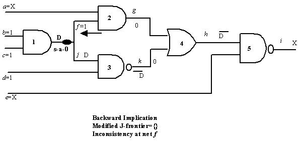
Figure 7(l): Inconsistency in net f
As discussed before, backtrack is required for this inconsistency. In this case, there was a choice of selecting values for input a and net f, by backward implication to set g =0; see Figure 7(l), where choice (i) was selected. Now let us backtrack by taking the other choice, i.e., a =0, f =X; this is shown in Figure 7(m). In Figure 7(m) all steps are undone (by making net values to X) required in this backtracking.
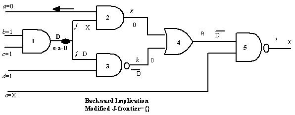 Figure 7(m): Backtrack by considering a =0, f=X for backward implication for g =0