Definition 3: Unique D-Drive
If there is only one gate in D-frontier, then fault effect has to be propagated through that gate. This situation is called unique D-drive.
Definition 4: J-frontier
The J-frontier comprises gates whose output value is known (0 or 1) but its inputs are not yet computed (or not yet implied by its inputs). In other words, output of a gate in the J-frontier is known, but inputs are not yet computed. This implies that, any gate in J-frontier can be used for justification. This is explained by an example given in Figure 2.
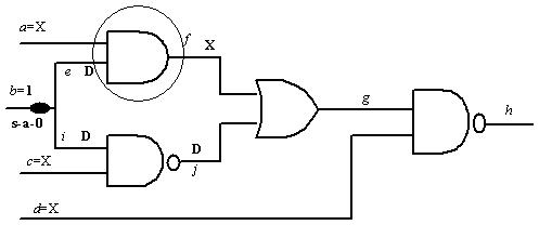
Figure 2. J-frontier--the encircled gates
We consider the same circuit as in Figure 1. Assume that it was decided that fault effect D be propagated via j. So, j =D by forward implication. Also, f = 0 for propagating D to g. Now, the encircled gate in Figure 2 is in the J-frontier, because the output is known as 0 and its inputs are X, which can be decided in justification step. The basic idea is, X at the inputs can be appropriately selected so that output is justified. In other words, during justification gates in J-frontier can only be considered. Once the inputs are justified, the gate is deleted from the J-frontier list.
Procedure 1: Implication
The implication procedure comprises 3 steps
- Compute all the values of the signals that can be determined uniquely from already given signal values (of some nets). If many choices are available, for example as in singular cover, any one of them can be considered.
- Maintain J-frontier and D-frontiers
- Check for consistency and stop in case of inconsistency (i.e., contradictory signal values are implied by the implication procedure).
Basically, implication procedure is similar to a simulation process where values of all nets (and finally primary outputs) are determined starting from primary inputs. However there are some differences between simulation and implication as discussed in Table 2.
Table 2: Simulation and Implication
Simulation |
Implication |
All the signal values are determined uniquely |
All signals may not be determined uniquely |
Value assignment moves from inputs to outputs of a circuit |
Signal assignments propagate both towards primary inputs and primary outputs. For example, to test a s-a-1 fault at net l say, we need to have implication in two directions (i) backwards, to primary inputs to make l=0 and (ii) forward, to primary outputs to propagate D. |
There is no inconsistency |
Inconsistency may arise, when for a given net l (which is not the fault location) different signal values (0 or 1) need to be assigned. |