1. Introduction
In the last module we have discussed about a new algebra called Routh’s algebra, which is suitable for ATPG using the “sensitize-propagate-justify” approach. In this chapter we will discuss Roth’s D-Algorithm [1] in depth, which is the first formal algorithm for ATPG. We will first start with the basic definitions and procedures required in D-algorithm. Following that we will explain D-algorithm with examples. Finally, we will see in brief, some issues in D-algorithm, and how they were addressed in some advanced algorithms.
2. Definitions and procedures
Now we will see some definitions and procedures required in D-algorithm.
Definition 1: Singular cover
Singular cover of a logic gate is the minimal set of input signal assignments needed to represent essential prime implicants in the Karnaugh map of the logic gate, both for the case 0 and case 1. Table 1 shows singular cover for 2 input AND and 2 input OR gate.
Table 1. Singular cover for 2 input AND and 2 input OR gate
AND |
Inputs |
Output |
|
OR |
Inputs |
Output |
||
|
0 |
X |
0 |
|
1 |
X |
1 |
|
|
X |
0 |
0 |
|
X |
1 |
1 |
|
|
1 |
1 |
1 |
|
0 |
0 |
0 |
|
From the table it may be noted that for 0 at the output of the AND gate only one input needs to be specified and the other is X. So we have 2 choices (0X and X0) for the singular cover of a 2-input AND gate for output =0. But for output =1 there is only one choice. Similarly, for the OR gate we have 2 choices (1X and X1) for the singular cover for output =1; for output=0 we have a single choice. In a similar way, singular cover for any gate can be found.
Definition 2: D-frontier
The D-frontier comprises gates whose output value is X and at least one of its input is D or ![]() . This implies that, any gate in D-frontier can be used for fault propagation. This is explained by an example given in Figure 1.
. This implies that, any gate in D-frontier can be used for fault propagation. This is explained by an example given in Figure 1.
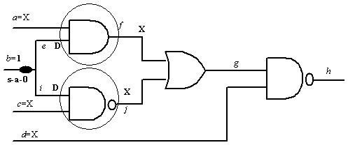
Figure 1. D-frontier-the encircled gates
In Figure 1, let us consider a s-a-0 fault at input line b. The only way to sensitize the fault is to make b=1. Automatically, nets e and i are assigned D. All other nets are assumed to have the value X. Now, D-frontier comprises gates which are encircled. It may be noted that in these gates one input is D and the other is X. The basic idea is, X at the inputs can be appropriately selected so that D or ![]() can be propagated to the output of the gates. In other words, faults can be propagated only through gates in the D-frontier. Once the fault is propagated (i.e., the output of the gate has D or
can be propagated to the output of the gates. In other words, faults can be propagated only through gates in the D-frontier. Once the fault is propagated (i.e., the output of the gate has D or ![]() ), the gate is deleted from the D-frontier list.
), the gate is deleted from the D-frontier list.