Mode shapes: Angular displacements at the beginning and end of various branches can be summarised as
| (6.96) |
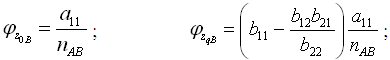 |
(6.97) |
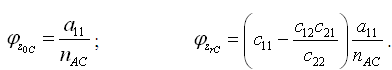 |
(6.98) |
On substituting one of the value of torsional natural frequencies obtained from equation (6.95) into equations(6.96) -(6.98), angular displacements at the beginning and end of various branches can be obtained. Then these may be substituted back into transfer matrices for each braches considered (i.e., equation(6.84) ), where upon the state vector at each station may be evaluated. The plot of angular displacements against shaft positions then indicates the system mode shapes corresponding to the chosen natural frequency. For other natural frequencies also similar steps have to be performed to get corresponding mode shapes.
Using this method, there will not be any change in the elastic line (mode shape) due to the gear ratio, since these have now already been allowed for in the analysis. Moreover, for the present case we have not gone for the equivalent system at all. For the case when the system can be converted to an equivalent single shaft, the equivalent system approach has the advantage. It should be noted that for the present case the DOF of the rotor system would be (p + q + r + 1). The total number of discs (including gears) is (p + q + r + 3), however, at junction the DOF of two gears (e.g., at 0th station of braches B and C) is related with the third (at pth station of branch A), hence, we would have two DOF less as compared to the number of discs in the system. Now, through numerical examples the procedure will be illustrated.
Example 6.12 For a geared system as shown in Figure 6.41, find torsional natural frequencies. The shaft ‘A’ has 5 cm diameter and 0.75 m length, and the shaft ‘B’ has 4 cm diameter and 1.0 m length. Take the modulus of rigidity of the shaft G equals to![]() , the polar mass moment of inertia of discs and gears are
, the polar mass moment of inertia of discs and gears are
![]()
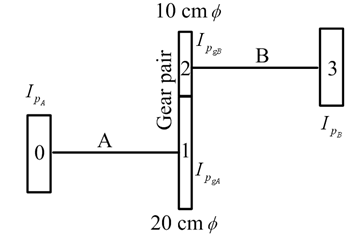
Figure 6.41 Two-discs with a geared system