3.3.3 Fluid-film dynamic force equations
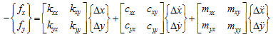
A model of a typical annual (or clearance) seal is shown in Fig. 3.32(a). The geometrical shape of a clearance seal is similar to that of a hydrodynamic bearing; however, they are different in the following aspects. To avoid contact between a rotor and a stator, the ratio of the clearance to the shaft radius in seals is made few times (2 to 10 times) larger than that of hydrodynamic bearings. The flow in seals is turbulent and in hydrodynamic bearings it is laminar. Therefore, unlike hydrodynamic bearing, one cannot use the Reynolds equation for analysis of seals. When a rotor vibrates, a reaction force of the fluid in the seal acts on the rotor. In case of a small vibration around the equilibrium position, the fluid force can be linearized on the assumption that deflections are small. The general governing equations of fluid-film forces on seals, which has small oscillations relative to the rotor, is given by the following linearized force-displacement model (Childs et al., 1986).
 |
(3.126) |
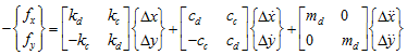
where fx and fy are fluid-film reaction forces on seals in x and y directions. k, c, m represent the stiffness, damping and added-mass coefficients, subscripts: xx and, yy represent the direct, and xy and yx represent the cross-coupled terms, respectively. These coefficients vary depending on the equilibrium position of the rotor (i.e., the magnitude of the eccentricity), rotational speed, pressure drop, temperature conditions, etc. The off-diagonal coefficients in equation (3.126) arise due to fluid rotation within the seal and unstable vibrations may appear due to these coefficients. Equation (3.126) is applicable to liquid annular seals. But for the gas annular seals, the added-mass terms are negligible. For small motion about a centered position (or with very small eccentricity) the cross-coupled terms are equal and opposite (e.g., kxy = -kyx = kc and cxy = -cyx = cc) and the diagonal terms are same (e.g., kxx = kyy = kd and cxx = cyy = cd) (Childs et al., 1986). Considering these relationships and neglecting the cross-coupled added-mass terms, equation (3.126) takes the following form
 |
(3.127) |
where subscripts: d and c represent direct and cross-coupled, respectively. The RDPs (rotor dynamic parameters) largely affect the performance of the turbomachineries as they lead to serious synchronous and sub-synchronous vibration problems. Whirl frequency ratio, f = kc /(cdω ) is a useful non-dimensional parameter for comparing the stability properties of seals. For circular synchronous orbits, it provides a ratio between the destabilizing force component due to kc and the stabilizing force component due to cd. In experimental estimation of RDPs of seals, these coefficients (of equation (3.126) and (3.127)) are determined with the help of measured vibrations data from a seal test rig.
The more recent textbooks on rotor dynamics include information on rotor dynamic characteristics of rotary seals. Vance (1988), Childs (1993), Krämer (1993), Rao (2000), Adams (2001) and Tiwari et al. (2005) provide a good introductory treatments of rotary seal dynamics.
3.4 Squeeze-Film Dampers
Squeeze-film dampers can be regarded as a fluid-film cylindrical bearing without the rotation of the journal. The fluid film gets the shearing action due to the relative translatory motion of the bearing (Fig. 3.52(a)) rather than the squeezing action due to the relative transverse motion of the damper (Fig. 3.52(b)). Squeeze-film dampers usage in attenuating vibrations is widespread in aircraft gas turbine industries as compared to the process industries where its preferred usage is as a band-aid solution without any preplanning. This is due to the reason that squeeze-film dampers are more complex to design than any other machine elements. The attenuation of subharmonic rotor instabilities would be the main concern in the designer mind while designing a squeeze-film damper since steady state synchronous vibrations are relatively easier to tackle with modifications in the rotor and the bearing parameters itself (Zeidan, et al., 1996).
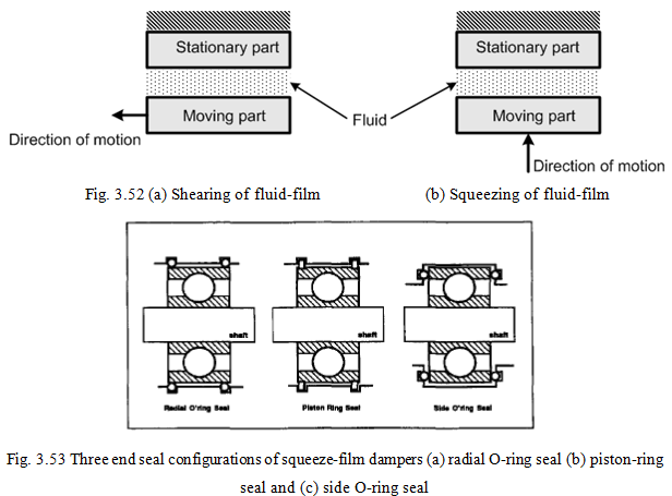
Squeeze-film dampers can be used in both for rolling bearings and fluid-film bearings by providing arrangement for the squeezing of the film (Fig. 3.52(b)) between the outer ring (or sleeve) and the housing, and the bearing bush (or sleeve) and the housing, respectively. The sleeve is slotted or pinned loosely to prevent its rotation. For rolling bearing three such arrangements are shown in Fig. 3.53, in which based on the seal shape (circular (O) or rectangular (piston) cross-section of seal rings) and its position, the damper classification is made. Since rolling bearings are extensively used in aircraft turbine engines and in such bearings the damping is very low. The squeeze-film damper is designed in series with rolling bearings provide enough damping to suppress unstable vibrations of the rotor system.
The performance of squeeze-film dampers depends upon several geometrical, physical and operating parameters. Some of them are geometrical parameters: the length, the diameter, the radial clearance, the feed and discharge mechanisms, the type of seal ends; physical parameters: the viscosity of the lubricant; operating parameters: the lubricant supply pressure, the fluid inertia, and dynamic cavitations. Similar to bearings, the incompressible-fluid Reynolds equation is generally used to model the squeeze-film dampers. However, because of cavitation phenomena, the correlation between theory and experiment are in dampers is less as compared to bearings.
Rotordynamic force coefficients
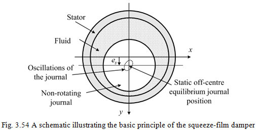
Similar to fluid film bearings, for squeeze-film dampers the fluid-film forces generated by small amplitude of oscillations about a static equilibrium (off-centre) position are useful for the stability analysis of rotating machinery. A schematic of squeeze-film geometry and the motion of journal performing small oscillations at an off-centered static equilibrium position are shown in Fig. 3.54, where es is the static eccentricity.
Since the damper can not provide any stiffening effect due to the non-rotating journal, hence, in general, the damper force will be
(3.128) |
and
(3.129) |