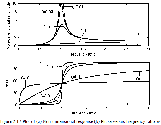
It can be seen from Figure 2.17(b), for a lightly under-damped system the phase angle changes from 0° to 90° as the spin speed is increased to ωnf (i.e., ![]() =1) and gradually becomes 180° as the spin speed is increased to a higher frequency ratio. It should be noted that the phase angle is 90° at
=1) and gradually becomes 180° as the spin speed is increased to a higher frequency ratio. It should be noted that the phase angle is 90° at ![]() =1 even for the case of various level of damping in the rotor system. For highly over-damped system the phase angle always remain at 90° before and after
=1 even for the case of various level of damping in the rotor system. For highly over-damped system the phase angle always remain at 90° before and after ![]() =1, which might be a physically unrealistic case to attain.
=1, which might be a physically unrealistic case to attain.
As the spin speed crosses the critical speed, the center of gravity of the disc comes inside of the whirl orbit and the rotor tries to rotate about the center of gravity (since the phase changes from 0° to 180° for undamped case). This can be seen from Figure 2.17(a) as the spin speed approaches infinity the displacement of the shaft tends to the equal to the disc eccentricity (![]() = 1). Since the measurement of amplitude of vibration at the critical speed is difficult, hence the determination of precise critical speed is difficult. To overcome this problem the measurement of the phase at critical speed is advantageous (since it remain constant at 90° irrespective of damping in the system). The change in phase between the force and the response is also shown in Figure 2.18 for three difference spin speeds, i.e., below the critical speed, at the critical speed, and above the critical speed.
= 1). Since the measurement of amplitude of vibration at the critical speed is difficult, hence the determination of precise critical speed is difficult. To overcome this problem the measurement of the phase at critical speed is advantageous (since it remain constant at 90° irrespective of damping in the system). The change in phase between the force and the response is also shown in Figure 2.18 for three difference spin speeds, i.e., below the critical speed, at the critical speed, and above the critical speed.
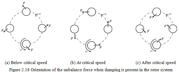
(a) Below critical speed |
(b) At critical speed |
(c) After critical speed |
|
Since for the present analysis the synchronous whirl condition is assumed, at a particular speed shaft will not have any flexural vibration and it (in a particular bend configuration) will whirl (orbiting) about its bearing axis as shown in Figure 2.16(a). It can be seen that the black point on the shaft cross-section will have compression during the whirling. However, it can be seen from Figure 2.16(b) for anti-synchronous whirl that the shaft (the black point on the shaft cross-section) will have reversal of the bending stresses twice per whirling of the shaft. For asynchronous whirl the black point on the cross-section of the shaft will take all the time different positions during whirling of the shaft.
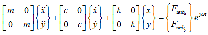
2.4.3: Steady-state response (Approach 3): With the development in software (Scilab, MATLAB, etc.), which can handle complex matrices, the following matrix procedure may be very helpful for the numerical simulation, which may be extended even for very complex multi-DOF rotor systems. Equations (2.29) and (2.30) can be combined in the matrix form as
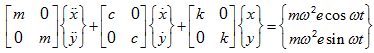 |
(2.55) |
The force vector in equation (2.55) could be expressed as
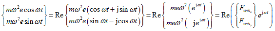 |
(2.56) |
with
(2.57) |
where Re(.) represents the real part of the quantity inside the parenthesis. ![]() and
and ![]() are the unbalance force components in x and y directions, respectively. On substituting equation (2.56) into equation (2.55), it can be written as (henceforth for brevity the symbol Re(.) will be omitted, since the left hand side expression is a real quantity)
are the unbalance force components in x and y directions, respectively. On substituting equation (2.56) into equation (2.55), it can be written as (henceforth for brevity the symbol Re(.) will be omitted, since the left hand side expression is a real quantity)
 |
(2.58) |