Substituting equation (2.38) into equation (2.35), it gives the displacement amplitude as
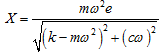 |
(2.39) |
Similarly, we can obtain the response amplitude in the y-direction from equation (2.30) as
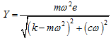 |
(2.40) |
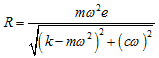
Above amplitudes could be plotted with respect to spin speed of the shaft for overall understanding of the response, and it will be seen in the next subsection. From equations (2.32), (2.33), (2.39) and (2.40), it can be seen that because of the symmetry of the rotor we have X = Y = R and the orbit is a circular in nature, i.e.,
(2.41) |
2.4.2: Steady-state response (Approach 2): An alternative approach that is very popular in rotor dynamics analyses is to use the complex algebra to define the whirl radius as
| r = x + jy | (2.42) |
where ![]() . On multiplying equation (2.30) by j and adding to equation (2.29), we get
. On multiplying equation (2.30) by j and adding to equation (2.29), we get
(2.43) |
Now the steady state response can be assumed as
(2.44) |
where R is the whirl amplitude (it is a real quantity), θ is the phase lag of response with respect to the unbalance force. Both R andθ are constant quantities. On differentiating equation (2.44) with respect to time, t, we get
(2.45) |
On substituting equations (2.44) and (2.45) into equation (2.43), we get
(2.46) |
Equation (2.46) can be written as
(2.47) |
On separating the real and imaginary parts of equation (2.47), we get
(2.48) |
and
(2.49) |
From equation (2.49), we get the phase as
(2.50) |
On substitution of the phase from equations (2.50) into (2.48), the whirl amplitude can be written as
 |
(2.51) |
Equations (2.49) and (2.51) are similar to previous results, i.e. equations (2.37) and (2.39), respectively. The non-dimensional form of equations (2.50) and (2.51) can be written as
(2.52) |
and
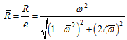 |
(2.53) |
with
(2.54) |
where ![]() is the whirl amplitude ratio,
is the whirl amplitude ratio, ![]() is the frequency ratio, ωnf is the transverse natural frequency of non-rotating rotor system,
is the frequency ratio, ωnf is the transverse natural frequency of non-rotating rotor system,![]() is the damping ratio, and cc is the critical damping for which the damping ratio is equal to unity. Fig. 2.17 shows the whirl amplitude and the phase variation with the frequency ratio. Figure 2.17(a) shows that the maximum amplitude (i.e., the location of the critical speed) occurs at
is the damping ratio, and cc is the critical damping for which the damping ratio is equal to unity. Fig. 2.17 shows the whirl amplitude and the phase variation with the frequency ratio. Figure 2.17(a) shows that the maximum amplitude (i.e., the location of the critical speed) occurs at ![]() = 1 for the undamped case; however, at slightly higher frequency ratio than one (i.e.
= 1 for the undamped case; however, at slightly higher frequency ratio than one (i.e. ![]() > 1), when damping is present in the system. It should be noted that we have observed previously that damped natural frequency is lesser than the undamped case. It could be observed that the damping is the most important parameter for reducing the whirl amplitude at the critical speed.
> 1), when damping is present in the system. It should be noted that we have observed previously that damped natural frequency is lesser than the undamped case. It could be observed that the damping is the most important parameter for reducing the whirl amplitude at the critical speed.