2.4 Jeffcott Rotor Model
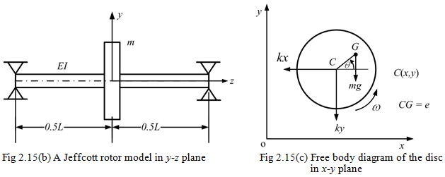
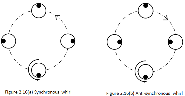
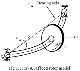
To overcome the limitations of the Rankine model, Jeffcott (1919) proposed a model and Figure 2.15 shows a typical Jeffcott (it is also called Föppl or Laval) rotor model. It consists of a simply supported flexible massless shaft with a rigid thin disc mounted at the mid-span. The disc center of rotation, C, and its center of gravity, G, is offset by a distance, e, which is called the eccentricity. The shaft spin speed is, ω, and the shaft whirls about the bearing axis with a whirl frequency, v. For the present case, the synchronous whirl is assumed (i.e., v = ω), which is prevalent in the case of unbalance responses. The synchronous motion also occurs between the earth and the moon, and due to this we see always the same face of the moon from the earth. In the synchronous motion of the shaft, the orbital speed and its own spin speed are equal as shown in Figure 2.16(a). The sense of rotation of the shaft spin and the whirling are also same (i.e., CCW for Fig. 2.16a). The black spot on the shaft represent the unbalance location or any other mark on to the shaft. The unbalance force, in general, leads to synchronous whirl conditions, hence this motion is basically a forced response.
Other kinds of whirl motions, which may occur in real systems, are: anti-synchronous (i.e., v = -ω; as shown in Figure 2.16(b)) and asynchronous (i.e., v ≠ ω). The anti-synchronous whirl may occur when there is rub between the rotor and the stator, however, it occurs very rarely. For this case, the sense of rotation of the shaft spin and the whirling are opposite. Asynchronous whirl motion may occur when speeds are high (e.g., when gyroscopic effects are predominate) or when the rotor is asymmetric or when dynamic properties of the bearing are anisotropic. The asynchronous whirl motion may occur even in the perfectly balanced rotor, and due to this it will have whirl frequency as one of the natural frequency of the rotor system as long as the rotor linear model is considered. The black mark on to the shaft will not be so systematic as in Figure 2.16 and may occupy various positions depending upon the frequency of whirl.
The transverse stiffness, k, of a simply supported shaft is expressed as
| (2.25) |
where E is the Young’s modulus, I is the second moment of area of the shaft cross-section, and L is the span of the shaft. and are coordinates to define the position of the centre of rotation of the rotor, C (Fig. 2.15c). Here o is the static equilibrium of the disc (for small deflection it can be approximated as if it is located at bearing axis as shown in Fig. 2.15a). The location of the unbalance is given by θ, which is measured from the x-axis in the counter clockwise direction. Thus, three geometrical coordinates (x, y,θ) are needed to define the position of the Jeffcott rotor (i.e., it has three-DOFs). The disc is at the mid-span, hence, the tilting of the disc about transverse axes (i.e., x and y) are not there.
Jeffcott rotor