From Figure 2.15(c), the force and the moment balance in the , and q directions can be written as
 |
(2.26)
(2.27) |
and
(2.28) |
where ![]() and
and ![]() are the position of the centre of gravity, G, of the disc; m is the mass and Ip is the polar mass moment of inertia of the disc. Apart from the restoring force contribution from the shaft, a damping force is also considered. The damping force is idealized as viscous damper and it is mainly coming from the support and aerodynamic forces at the disc. The material damping of the shaft is not considered, which may leads to the instability in the rotor and it will be considered in detail in subsequent Chapter 11.
are the position of the centre of gravity, G, of the disc; m is the mass and Ip is the polar mass moment of inertia of the disc. Apart from the restoring force contribution from the shaft, a damping force is also considered. The damping force is idealized as viscous damper and it is mainly coming from the support and aerodynamic forces at the disc. The material damping of the shaft is not considered, which may leads to the instability in the rotor and it will be considered in detail in subsequent Chapter 11.
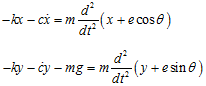
For the case θ = ωt, i.e., when the disc is rotating at a constant spin speed, the Jeffcott rotor model reduces to two-DOF rotor model. Physically it means that only the transverse vibration is considered and the torsional vibration is ignored. By considering the static equilibrium as the reference for the axis system, the gavity effect could be neglected. For the case when the reference axis is at bearing axis position then gavity force would give a constant deflection along with the unbalance response. The non-linear effect of gravity will be considered when we will discuss the sub-critical speed phenomenon in Chapter 11. Hence, equations of motion in the x and y directions, from equations (2.26) and (2.27), can be written as
(2.29) |
and
(2.30) |
In deriving equations of motion, the centrifugal force due to unbalance is not considered as external force, however, it has been accounted in the inertia force in the form of eccentric position of the disc centre of gravity as given in equations (2.26) and (2.27). It should be noted that above equations of motion are uncoupled, and motion can be analysed independently in two transverse planes (i.e. z-x and y-z planes). Noting equation (2.8), from the undamped free vibration analyses it can be seen that since the rotor system is symmetric, the rotor system will have two equal transverse undamped natural frequencies in two orthogonal directions and are given as
(2.31) |
Since both are natural frequencies same, hence a single frequency is observed during the whirling of rotor in two orthogonal planes. However, for an anisotropic rotor support system these will be distinct as we shall observe in Chapter 3.
2.4.1: Steady-state response (Approach 1): The damping does not affect the natural frequency of the system appreciably. However, its effect is more predominant for suppressing the vibration amplitude at the resonance. Steady state forced responses of equations (2.29) and (2.30) can be assumed as
(2.32) |
and
(2.33) |
where X and Y are the steady state forced response amplitude in the x and y directions, respectively; ω is same as the excitation frequency due to the unbalance force and is equal to the shaft spin speed (synchronous condition is assumed), Φ is the phase lag of the displacement, x(t), with respect to the unbalance force. The phase difference between the two orthogonal direction responses for the direction of spinning of the shaft chosen is ![]() radian. For the direction of shaft whirling shown in Figure 2.15 (i.e., counter clockwise; CCW) for the present axis system, the response in y-direction will lag the response in x-direction by
radian. For the direction of shaft whirling shown in Figure 2.15 (i.e., counter clockwise; CCW) for the present axis system, the response in y-direction will lag the response in x-direction by ![]() radian. Hence the lag of the y-direction response with respect to the force will be (
radian. Hence the lag of the y-direction response with respect to the force will be (![]() +Φ). On taking the first and second time derivatives of the response, x(t), we get
+Φ). On taking the first and second time derivatives of the response, x(t), we get
(2.34) |
On substituting equations (2.32) and (2.34) into equation (2.29), we get
![]()
which could be expanded as
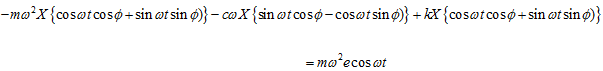
On separating the in-phase (i.e., cosωt) and quadrature (i.e., sinωt) terms of above equation, we get
(2.35) |
and
(2.36) |
Equation (2.36) can be solved for the phase angle, as
(2.37) |
which gives
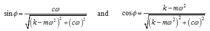 |
(2.38) |