Unbalances in Two or More Planes :
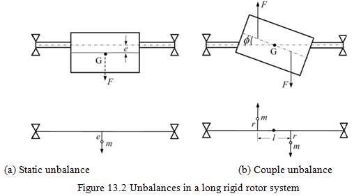
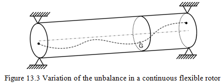
Figure 13.2 shows two types of unbalance in a rigid rotor system. The rotor consists of a rigid rotor and a massless elastic shaft. First (Fig. 13.2a) is the static unbalance , which is the state represented by a geometric eccentricity, e , of the center of a gravity of a rotor from the centerline or rotational axis of the shaft. The unbalance produces a centrifugal force proportional to the square of the rotational speed. This static unbalance can be detected without operating the rotor since the unbalance is always directed downward if the shaft is supported horizontally by bearings having little friction. Theoretically, it is similar to the single plane unbalance described above, except the unbalance in uniformly distributed along the length of the rigid rotor. Second type of unbalance is couple unbalance,which is the state represented by the angular misalignment of the principal axis of mass moment of inertia of the rotor with respect to the centerline or rotational axis of the shaft. The magnitude of the couple unbalance ![]() is determined by the angle as shown in Figure 13.2b. This type of unbalance cannot be detected without rotating the shaft. Since the centre of gravity lies on the axis of rotation of the rotor, it could be in stable position at any orientation of the rotor, unlike the static unbalance. Figure 13.2(a and b) shows these unbalances as models with one and two concentrated masses, respectively. That means static unbalance can be balanced by a single plane balancing and couple unbalance has to balance with two balancing planes. With the above definition now the dynamic unbalance in a rigid rotor means the state with both the static and couple unbalances. (i.e., combination of Figures 13.2a and b). However, for such a case also two-plane balancing will be enough. On the other extreme case would be the unbalances in a continuous rotor (i.e., a flexible rotor with distributed mass) as shown in Figure 13.3. In this case eccentricity and its angular orientation may change in three-dimension continuously from one end of the shaft to another. Here we require N plane balancing, where
is determined by the angle as shown in Figure 13.2b. This type of unbalance cannot be detected without rotating the shaft. Since the centre of gravity lies on the axis of rotation of the rotor, it could be in stable position at any orientation of the rotor, unlike the static unbalance. Figure 13.2(a and b) shows these unbalances as models with one and two concentrated masses, respectively. That means static unbalance can be balanced by a single plane balancing and couple unbalance has to balance with two balancing planes. With the above definition now the dynamic unbalance in a rigid rotor means the state with both the static and couple unbalances. (i.e., combination of Figures 13.2a and b). However, for such a case also two-plane balancing will be enough. On the other extreme case would be the unbalances in a continuous rotor (i.e., a flexible rotor with distributed mass) as shown in Figure 13.3. In this case eccentricity and its angular orientation may change in three-dimension continuously from one end of the shaft to another. Here we require N plane balancing, where ![]() and generally for balancing up to mth mode N = m for
and generally for balancing up to mth mode N = m for ![]() .
.
13.2 Principle of Rigid Rotor Balancing
Now some basic principle of rigid rotor balancing will be outlined and this will pay the way to understand balancing methods for practical rotors.
13.2.1 Static Balancing (Single plane balancing)
The unbalance force, for a single plane disc as shown in Fig. 13.1, is given as
![]()
where ω is the spin speed of the rotor. If we want to know correction mass, mc, at a radius of r , it will be given by
![]()
The correction should be placed 180 0 away from unbalance mass m . Such a correction is called a single plane balancing of the rotor, which eliminates the inertia forces transmitted to the foundation (or bearing).