Till last chapter, we concentrated on transverse and torsional vibration analyses of rotor-bearing systems, e.g., free vibrations, forced responses and instability analysis. These analyses are very much useful tool for designers of rotating machineries to predict the behaviour of such machineries before actually their manufacturing and commissioning. These analyses help in the modification of design if operating speed is close to critical speeds or in instability zones. In the present and subsequent chapters, we will address another class of practical and the most common problems related to rotating machineries that practicing engineers face during the commissioning of new rotating machine, during operation, or after every major overhaul of such machineries. Some of these fault are unbalances, misalignments, rotor-stator rubs, bent or bowed shafts, fatigue cracks, the wear and tear of various moving and stationary components, loose components, and faults related to components of bearings, gears, coupling, blades, seals, etc. Among various kinds of faults, the most common fault is inherent unbalances (or residual unbalances) in machineries occur due to manufacturing error (fits and tolerances), material in-homogeneity, improper commissioning, thermal deformation, the wear and tear during operation, residual stresses, and so on. Basic definition of the unbalance and its type for rigid rotors has been introduced earlier in Chapter 2. To prevent excessive vibration due to unbalances, we must first decrease this unbalance (or balance the rotor), which is the major source of vibration.
In the present chapter, the procedure of static and dynamic balancing of rotor will be discussed in great details. For dynamic balancing, rotors are classified in two major categories, e.g., balancing of the rigid and flexible rotors. In fact, the same shaft of a rotor can be considered as rigid if it is operating much below its first critical speed and the flexible when it is operating near or above the first critical speed. That is why sometime it is also called the slow and high speed rotor balancing, respectively. Basic principles of rigid and flexible rotor balancing are quite different. Necessary principles and theories for dynamic balancing will be outlined before describing practical methods of balancing. For rigid rotor balancing two methods are described, e.g., the conversional cradle balancing machine method (off-site or off-field balancing) and the modern influence coefficients method (on-site or field balancing). Similarly, for the flexible rotor two basic methods are available, e.g., the modal balancing method and the influence coefficient method. In general, the rigid rotor can be balanced by putting correction masses in two balancing planes, however, in flexible rotor case it can be balanced by N balancing planes, where N is the number of flexible modes need to be balanced. Often, it is suggested to balance flexible rotor by ( N +2) balancing planes (i.e., to balance rigid rotor modes by 2 planes at low speeds and to balance flexible rotor modes by N planes at high speeds).
The unbalance in rotors will not only cause rotor vibrations, but also transmit rotating forces to the bearings and to foundation structures. The force thus transmitted may cause damage to the machine parts and its foundation. If the transmitted force is large enough, it might affect even the neighbouring machines and structures. Thus, it is necessary to remove the residual unbalance of a rotor, to as large an extend as possible, for its smooth running. Experimental estimation the residual unbalance in rotor-bearing system is an age-old problem. From the state of the art of the unbalance estimation, the unbalance can be obtained with fairly good accuracy (Kellenburger, 1972; Drechsler, 1980; Gnilka, 1983; Krodkiewski et al ., 1994; Darlow, 1989, Mindez-Ariani, 2005 ). Now the trend in the unbalance estimation is to reduce the number of test runs required, especially for the application of large turbogenerators where the downtime is very expensive ( Edwards et al., 2000; Tiwari , 2005 ).
13.1 Unbalances in the Rigid and Flexible Rotors
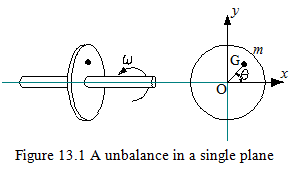
Unbalance in a Single Plane : Such unbalance occurs in gear wheels, grinding wheels, single stage compressors, blades of wind mills, the propeller of aircraft engines, etc. Figure 13.1 shows a rigid thin disc with the single plane unbalance. O is the centre of rotation of the disc and G is the centre of gravity of the rotor. The eccentricity, e , is defined as a distance between the centre of rotation and the centre of gravity, in practice the tolerable eccentricity would be of the order of μm (however, it will very much depend upon the type of applications). The unbalance in the disc is defined as
![]()
where is the unbalance with a unit of kg-m or g-mm, m is mass of disc, e is the eccentricity in the disc (length OG in Fig. 13.1). Even the order of eccentricity is very less for large rotors, which generally runs at high speed, the effect of unbalance force (meω2) could be devastating.