If the cutting plane appears as an edge in the top and front views and is normal in the profile view, it is a profile cutting plane. The left (or right) half of the object is "removed" and the left (or right) side view is drawn in section. A profile cutting plane is shown by BB in figure 14.
Multiple sections can be done on a single object, as shown in the figure 14. In this example, two cutting planes are used: one a horizontal and the other a profile cutting plane. Both cutting planes appear on edge in the front view, and are represented by cutting plane lines A-A and B-B, respectively. Each cutting plane will create a section view, and each section view is drawn as if the other cutting plane did not exist.
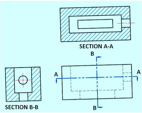
Figure 14. shows a profile cutting plane.
Section Line Practices
Section lines or cross-hatch lines are added to a section view to indicate the surfaces that are cut by the imaginary cutting plane.
Different section line symbols can be used to represent various types of materials.
However, there are so many different materials used in engineering design that the general symbol (i.e., the one used for cast iron) may be used for most purposes on engineering drawings.
The actual type of material required is then noted in the title block or parts list or as a note on the drawing. The angle at which lines are drawn is usually 45° degrees to the horizontal, but this can be changed for adjacent parts shown in the same section. Also the spacing between section lines is uniform on a section view.