Full Section View
A full section view is made by passing the imaginary cutting plane completely through the object. As shown in figure 21, all the hidden features intersected by the cutting plane are represented by visible lines in the section view. Surfaces touched by the cutting plane have section lines drawn at a 45-degree angle to the horizontal. Hidden lines are omitted in all section views unless they must be used to provide a clear understanding of the object. The top view of the section drawing shows the cutting plane line, with arrows pointing in the direction of line of sight to view the sectioned half of the object. In a multi-view drawing, a full-sectioned view is placed in the same position that an un-sectioned view would normally occupy, I.e., a front section view would replace the traditional front view.
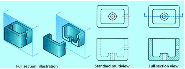
Figure 21 shows a full section view of an object.
Half Section view
Half sections are created by passing an imaginary cutting plane only halfway through an object. Hidden lines are omitted on both halves of the section view. Hidden lines may be added to the un-sectioned half, for dimensioning or for clarity. External features of the part are drawn on the un-sectioned half of the view. A center line, not an object line, is used to separate the sectioned half from the un-sectioned half of the view. The cutting plane line shown in the top view. The cutting plane line in the top view is bent at 90° and one arrow is drawn to represent the line of sight needed to create the front view in section. Half section views are used most often on parts that are symmetrical, such as cylinders. Also, half sections are commonly used in assembly drawings when external features are also to be shown. Figure 22 shows a half section view of an object.
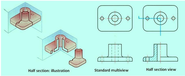
Figure 22 shows the cutting plane passing halfway through an object and one quarterof the object being removed