Cutting plane lines are thick (0.7 mm) dashed lines, that extend past the edge of the object 6 mm and have line segments at each end drawn at 90 degrees and terminated with arrows. The arrows represent the direction of the line of sight for the section view and they point away from the sectioned view. Two types of lines are acceptable for cutting plane lines in multi-view drawings. The normal representation of cutting plane lines are shown in figure 12. Line B-B is composed of alternating long and two short dashes, which is one of the two standard methods. The length of the long dashes varies according to the size of the drawing, and is approximately 20 to 40 mm. For a very large section view drawing, the long dashes are made very long to save drawing time. The short dashes are approximately 3 mm long. The open space between the lines is approximately 1.5 mm. Capital letters are placed at each end of the cutting plane line, for clarity or when more than one cutting plane is used on a drawing. The second method used for cutting plane lines is shown by line C-C, which is composed of equal-length dashed lines. Each dash is approximately 6 mm long, with a 1.5 mm space between.
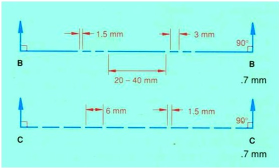
Figure 12 Normal representation of cutting plane lines.
Placement of Cutting Plane Lines
Cutting plane lines are only added to a drawing for clarity. If the position of the cutting plane is obvious, the line need not be drawn. Also, if the cutting plane line is in the same position as a center line, the cutting plane line has precedence.
In figure 10, the cutting plane appears as an edge in the top view and is normal in the front view; therefore, it is a frontal cutting plane. The front half of the object is "removed" and the front view is drawn in section.
If the cutting plane appears as an edge in the front view and is normal in the top view, it is a horizontal cutting plane. The top half of the object is "removed" and the top view is drawn in section. Figure 13 shows a horizontal cutting plane.
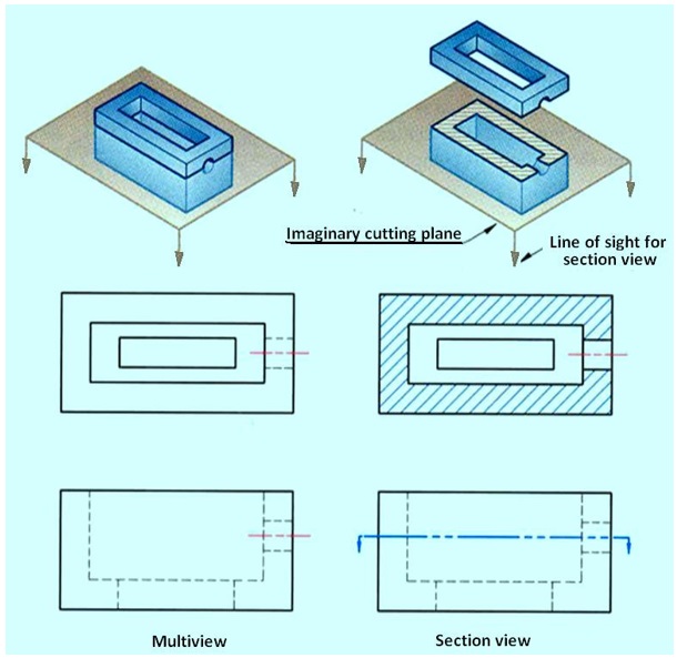
Figure 13. A horizontal cutting plane.