Visualization of Section Views
Figure 7 is multi-view drawing of a part that may be difficult to visualize in its 3-D form, because of the many hidden lines.
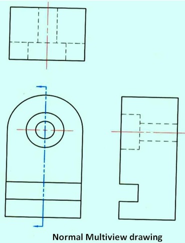
Figure 7 A multiview drawing of an object
A section view is created by passing an imaginary cutting plane vertically through the center of the part. Figure 8 is a 3D representation of the part after it is sectioned. The section view more clearly shows the interior features of the part. In the left corner of the figure, the cutting plane arrows, in the front view, point to the left, to represent the direction of sight for producing a right side view in full section. The direction of the arrow can also be thought of as pointing toward the half of the object being kept. The right half of the object is "removed" to reveal the interior features of the part. The line of sight for the section view is perpendicular to the cut surfaces, which means they are drawn true size and shape in the section view. Also, no hidden lines are drawn and all visible surfaces and edges behind the cutting plane are drawn as object lines. The corners of the section view are numbered as shown in the right hand figure so that they can be compared with the orthographic section view.
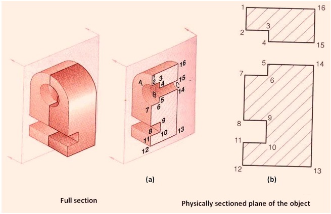
Figure 9 showing a full section and the physically sectioned plane of the object
The representation of the section view of the object shown in figure 9 is shown as (b) in figure 10. The section view in figure (a) shows only those surfaces touched by the cutting plane. Since conventional practice requires that features behind the cutting plane be represented, the change of planes between the two holes in the counter bored hole are shown in figure (b). If the section is viewed along the line of sight identified by the arrows in figure (c), arcs A, B, and C will be visible and should be represented as lines. In figure (b), the lines are 2-7,4-5,15-14. The counter bore and through holes are represented as rectangular features 2-7-6-3, and 4-5-14-15. All the surfaces touched by the cutting plane are marked with section lines. Because all the surfaces are the same part, the section lines are identical and are drawn in thesame direction. The center line is added to the counter bored hole to complete the section view.