Section Views
Introduction
In engineering industries, when the internal structure of an object is complicated, it is very difficult to visualize the object from its orthographic views since there will be several hidden lines. In such case, the internal details are shown by sectional views. Sectional views are an important aspect of design and documentation since it is used to improve clarity and reveal interior features of parts.
Sectional drawings are multi-view technical drawings that contain special views of a part or parts, that reveal interior features. A primary reason for creating a section view is the elimination of hidden lines, so that a drawing can be more easily understood or visualized. Traditional section views are based on the use of an imaginary cutting plane that cuts through the object to reveal interior features. This imaginary cutting plane is controlled by the designer and are generally represented by any of the following:
(a) Full section view, where the section plane go completely through the object. Example shown in figure 1.
(b) Half section view, where the section plane go half-way through the object. Example shown in figure 2.
(c) Offset section, where the sectional plane bent through the features that are not aligned. Example shown in figure 3.
(d) Broken-out section where the section go through part of the object . Example shown in figure 4.
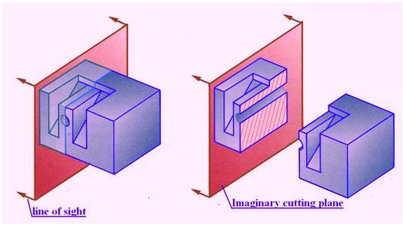
Figure 1. Illustrates a full Section view
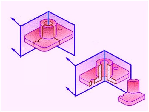
Figure 2. Illustrating a half section view
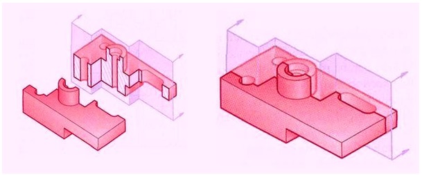
Figure 3. Illustrating an offset section
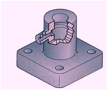
Figure 4. Illustrating a Broken-out Section