Operation of PM Machine Supplied by DC-AC Converter with 180° Mode of Operation
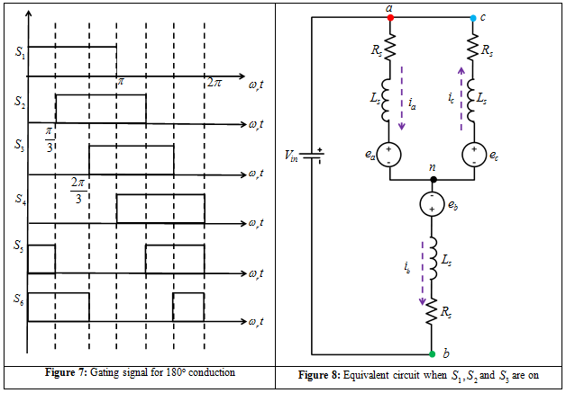
In this mode of operation at any point of time at least three switches are on. The gating sequence for this mode of operation is shown in Figure 7. The equivalent circuit of the PM machine, when switches S1, S5 and S6 are on, is shown in Figure 8. The set of equations defining the circuit configuration in Figure 8 is
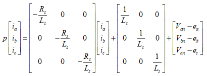 |
(6) |
where 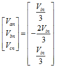
The solution of equation 6 is given in Lecture 22.
Suggested Reading:
[1] D. C. Hanselman , Brushless Permanent Magnet Motor Design , Magna Physics Pub, 2006