Given the number of turns (Nturns), then the flux linkages (λ) are equal to the product NturnsΦ. The induced emf is equal to the rate of flux linkages and is given by (Figure 3):
where λm = NturnsΦm |
(2) |
The –ve sign in equation 2 indicates that the induced e.m.f opposes the applied voltage. Some observations based on equation 2 are:
- The emf is proportional to the product of the rotational frequency and air gap for a constant number of turns.
- Assuming that air gap flux is constant, it can be seen that the e.m.f is influenced only by the rotational speed of rotor ωr which is same as the stator current frequency (because the PM machines are synchronous speed)
- By changing the frequency of stator current, the speed of the motor can be changed and a speed control of the motor can be achieved. However, beyond a certain speed known as base speed, an increase in stator frequency will result in voltage demand exceeding the supply capability. During that operation, keeping the voltage constant and increasing the excitation frequency reduces the airgap flux and thus allowing the excitation frequency reduces the air gap flux, thus allowing going to higher speed over and above the base speed. This operation is known as flux weakening .
The PM machines are fed by DC-AC converter. By changing the frequency at which the gates are turned on, the frequency of the output wave can be varied. In the next sections the operation of a three phase PM machines with 120° and 180° conduction modes are explained. The following assumptions are made in the following analysis:
- The phases of the machines are Y connected.
- The current entering the neutral point (n) is considered to be positive and leaving it is considered to be negative.
- The back e.m.f induced in the phases is sinusoidal.
- All the phases of the machine are balanced, that is, the inductances and resistances of the phases are equal.
Operation of PM Machine Supplied by DC-AC Converter with 120° Mode of Operation
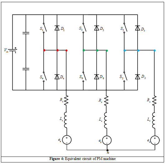
The equivalent circuit of the PM machine motor is shown in Figure 4. When the motor is operated in 120° then at given point of time only two switches conduct and six switching combinations are possible. The gating signals are shown in Figure 5. At angle ![]() the gate S6 turns off and the gate S2 is turned on. Hence, phase B is the outgoing phase and C is the incoming phase. Since the machine windings have inductance, the current through the phase B (ib) cannot become zero instantaneously. Thus, the current through the phase B continues to flow through the freewheeling diode D3 if ib < 0 or D6 if ib > 0.
the gate S6 turns off and the gate S2 is turned on. Hence, phase B is the outgoing phase and C is the incoming phase. Since the machine windings have inductance, the current through the phase B (ib) cannot become zero instantaneously. Thus, the current through the phase B continues to flow through the freewheeling diode D3 if ib < 0 or D6 if ib > 0.