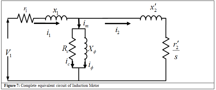
After referred the rotor quantities towards stator, the combined equivalent circuit of the machine is shown in Figure 7 . For simplicity the prime notations will not be used in the further discussions and all the rotor quantities henceforth will be referred to the stator side. Moreover, all the quantities are at stator frequency.
Simplification Equivalent Circuit
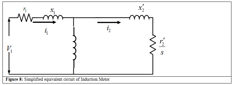
The use of exact equivalent circuit is laborious; hence some simplifications are done in the equivalent circuit. Under normal operating conditions of constant voltage and frequency, core loss in induction motors is usually constant. Hence, the core loss component can be omitted from the equivalent circuit, Figure 8 . However, to determine the shaft power, the constant core loss must be taken into account along with friction, windage and stray load losses. It should be noted that all the quantities used in the equivalent circuit are per phase quantities. Steady state performance parameters of the induction motor, such as current, speed, torque, losses etc. can be computed from the equivalent circuit shown in Figure 8 .
|