From equation 4 it can be seen that the resultant flux has amplitude of 1.5 Φm, is a sinusoidal function of angle θ and rotates in synchronism with the supply frequency. Hence, it is called a rotating field .
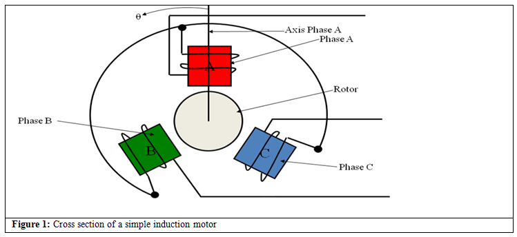
Principles of Operation of Induction Motor (Graphical Treatment)
Let the synchronous frequency ω be 1rad/sec. Hence, the spatial distribution of resultant flux at t=0sec, t=60sec, t=120sec, t=180 sec, t=240sec and t=300sec and are shown in Figure 2. The explanation of the flux creation is as follows
- At t=0, phase A is a maximum north pole, while phase B and phase C are weak south poles, Figure (2a) .
- At t=60, phase C is a strong south pole, while phase B and phase A are weak north poles Figure (2b) .
- At t=120, phase B is a strong north pole, while phase A and phase C are weak south poles Figure (2c) .
- At t=180, phase A is a strong south pole, while phase B and phase C are weak north poles Figure (2a) .
- At t=240, phase C is a strong north pole, while phase A and phase B are weak south poles Figure (2e) .
- At t=300, phase B is s strong south pole, while phase C and phase A are weak north poles Figure (2f) .